Rotor restraining apparatus and method for wind turbines

a technology of restraining apparatus and wind turbine, which is applied in mechanical equipment, machines/engines, and final product manufacture, etc., can solve the problems of increased space in the housing, inconvenient locking pin arrangement, and relatively insecureness

Active Publication Date: 2021-10-28
VESTAS WIND SYST AS
View PDF0 Cites 1 Cited by
  • Summary
  • Abstract
  • Description
  • Claims
  • Application Information

AI Technical Summary

Benefits of technology

[0009]The restraining member may be movable in that at least some component of its movement is substantially in the axial direction. The axial direction is defined by the rotational axis of the rotor. Also within the scope of the invention is that the movement is not exactly along the rotational axis of said rotor as long as the movement is substantially in this direction and the same effect is achieved. For instance, in one embodiment the at least part-circular locking element could be mounted slightly off-axis of the rotor axis, in which case a movement along the axis of the locking element would cause the same effect. Further, a movement substantially along the rotational axis but instead in a direction slightly inclined towards the rotational axis would also lead to the same effect of locking but may even facilitate an easier locking sequence, as there may be initially a looser fit between the teeth, and then a tighter fit as the locking member is moved further towards the locking ring. This effect may have similar effects as described further later with respect to tapering of the teeth.
[0019]This tapering of the engagement formations of the locking element allows for easier engagement of the formations with those of the locking element. It can also prevent excessive play between the locking element and the restraining member when in the restraining position.
[0021]One embodiment of another aspect of the invention can provide a method of restraining a wind turbine rotor using a rotor restraining apparatus as described herein, a rotational axis of said rotor defining an axial direction, the method comprising: rotating the locking element to a position at which the locking element engagement formations permit axial movement of the restraining member engagement formations; and moving the restraining member substantially along said axial direction from the non-restraining position to the restraining position so that the restraining member engagement formations are able to engage the locking element engagement formations.

Problems solved by technology

However, with the advent of larger turbine mechanisms, such a locking pin arrangement may not be appropriate, as the torque produced by the larger rotors could be sufficient to prevent locking with such pins, or to cause damage to the pins preventing proper use.
However, these radially applied brakes require additional space in the housing, and may also be relatively insecure even at low rotor torques, without considering the larger rotors coming into use.
A further problem with such serrated locking mechanisms may be that although the serrations are designed to cooperate or mesh to lock the rotor, it may nevertheless be difficult to get the corresponding serrations to engage each other properly, without additional fine rotational movement of the rotor and / or the locking brake.
In addition, there can be an amount of play left in the system if the serrations do not match exactly, have become worn, or do not cooperate precisely.
This can prevent adequate restriction of movement for maintenance, particularly for parts difficult to access, such as the turbine gear box.

Method used


Image

  • Rotor restraining apparatus and method for wind turbines
  • Rotor restraining apparatus and method for wind turbines
  • Rotor restraining apparatus and method for wind turbines

Examples


Embodiment Construction

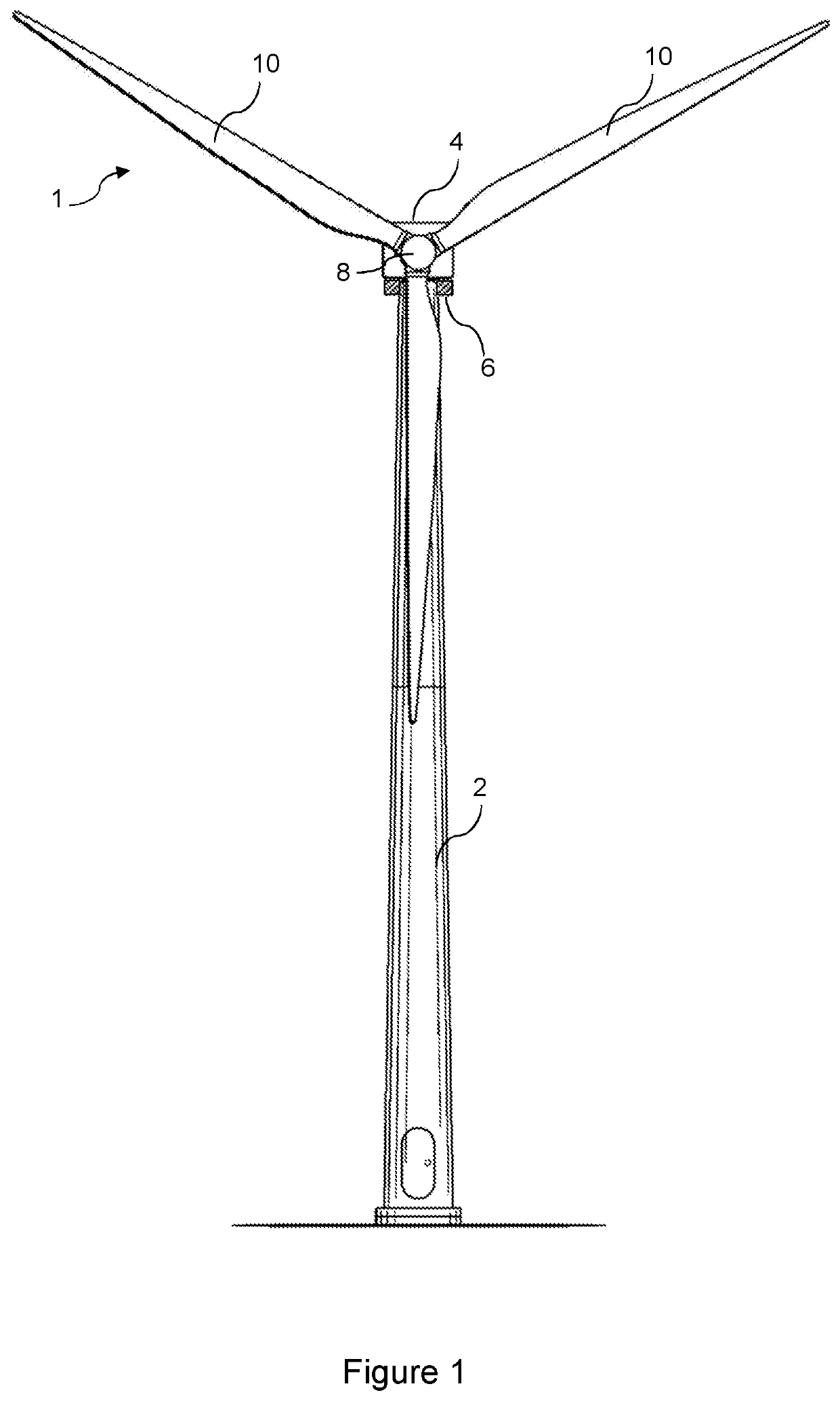
[0032]Referring to FIG. 1, a wind turbine 1 according to an embodiment of the invention comprises a tower 2, a nacelle 4 rotatably coupled to the top of the tower 2 by a yaw system 6, a rotating hub 8 mounted to the nacelle 4 and a plurality of wind turbine rotor blades 10 coupled to the hub 8. The nacelle 4 and rotor blades 10 are turned and directed into the wind direction by the yaw system 6. The nacelle 4 may house generating components of the wind turbine, including the generator, gearbox, drive train and brake assembly, as well as convertor equipment for converting the mechanical energy of the wind into electrical energy for provision to the grid. It may be noted that “direct drive” wind turbines that do not use gearboxes are also known; a gearbox may therefore be optional.

[0033]The nacelle 4 also necessarily contains a main shaft housing (not shown in FIG. 1), which houses a main rotor shaft that is connected at a forward end to the hub 8 and rotor blades 10, and at a rear en...


PUM


Abstract

Rotor restraining apparatus (200) and methods for a wind turbine (1) are disclosed. A rotor restraining apparatus has a locking element (204) associated with a rotor (8, 203) of the wind turbine, a rotational axis of said rotor defining an axial direction, the locking element being at least part-circular in form. The locking element comprises a plurality of engagement formations (205) disposed on a periphery thereof. The apparatus also has a restraining member (206), comprising a plurality of engagement formations (207). The restraining member is movable substantially along said axial direction between: (a) a non-restraining position; and (b) a restraining position in which the restraining member engagement formations are able to engage the locking element engagement formations. At least a portion of the restraining member has an arcuate form that substantially matches the curvature (A) of the locking element.

Description

FIELD OF THE INVENTION[0001]This invention is directed to types of rotor restraining apparatus for wind turbines, and methods of operating such rotor restraining apparatus.BACKGROUND OF THE INVENTION[0002]Wind turbines for power generation are well known in the art. In a common arrangement, a nacelle is mounted on a tower, with a rotor and blades being mounted on the nacelle. The rotor is mounted on a rotor shaft which is supported in the nacelle by a shaft housing.[0003]In certain situations, the rotor must be stopped, maintained in position, or locked to prevent any rotary movement, for example so that maintenance work can be carried out on the rotor or nacelle. In general, rotor braking and locking mechanisms are known. In one previously considered arrangement, a locking hub is mounted on the rotor shaft. The locking hub is a radial flange with holes that can be engaged by locking pins mounted to and movable to and from the housing. However, with the advent of larger turbine mech...

Claims


Application Information

Patent Timeline
Patent Type & Authority Applications(United States)
IPC IPC(8): F03D7/02
CPCF03D7/0268F05B2260/31F05B2240/211F03D7/0248F05B2230/60F03D80/00Y02E10/72Y02P70/50
Inventor LIINGAARD, ANDERS HASLUNDTHERKILDSEN, CLAUS HALD
Owner VESTAS WIND SYST AS
Why Eureka
Try Eureka