Ultra low power mesh network

a low power, mesh network technology, applied in the direction of substation remote connection/disconnection, high-level techniques, climate sustainability, etc., can solve the problems of 4 minutes of wifi, no centralized timing or transmission, and inacceptable for most purposes, and achieve the effect of faster data ra

Active Publication Date: 2020-08-11
SILICON LAB INC
View PDF7 Cites 1 Cited by
  • Summary
  • Abstract
  • Description
  • Claims
  • Application Information

AI Technical Summary

Benefits of technology

[0053]On the wake-up pattern transmission as it relates to prior art Access Points (AP) and other equipment which predates the present invention, a particular advantage of the wakeup-transmitter mode 302 is that any existing prior art WiFi device which is able to be firmware upgraded can form wake-up packets according to the present invention, since WLAN packets with arbitrary data contents can be formed into a wakeup sequence easily, with the packet length selected to form the “1” pattern and non-transmission forming the “0” pattern of the first and second wakeup sequence, and both the mesh device and the prior art WiFi device are already fully capable of communication once the mesh device is awake using prior art WLAN methods and standards. In this manner, the prior art WLAN device can easily be firmware upgraded to transmit the wakeup sequence as a series of packets and packet gaps.

Problems solved by technology

One issue is that the network needs to find a route from each station to a gateway such as AP1, and another issue is that there is no centralized timing or transmission as infrastructure mode provides.
Accordingly, just 10 hops through a mesh network has a latency of 20 s (˜4 min) for Bluetooth and 4 minutes for WiFi, which are unacceptable for most purposes.
Another problem of the prior art is that for dynamically changing networks, a significant amount of power is consumed with RF advertising, in the case of Bluetooth (Bluetooth Low Energy, known as BLE), where the slave device has an advertising interval and the master device has a scan window and scan interval.
As the below table shows, short Bluetooth connection times require the advertising window and scan interval both be short, which greatly increases battery drain.
For Bluetooth Long Range (BLR), the problem is exacerbated over BLE by the increased BLR transmit frames and requirement for low duty cycle.

Method used


Image

  • Ultra low power mesh network
  • Ultra low power mesh network
  • Ultra low power mesh network

Examples


Embodiment Construction

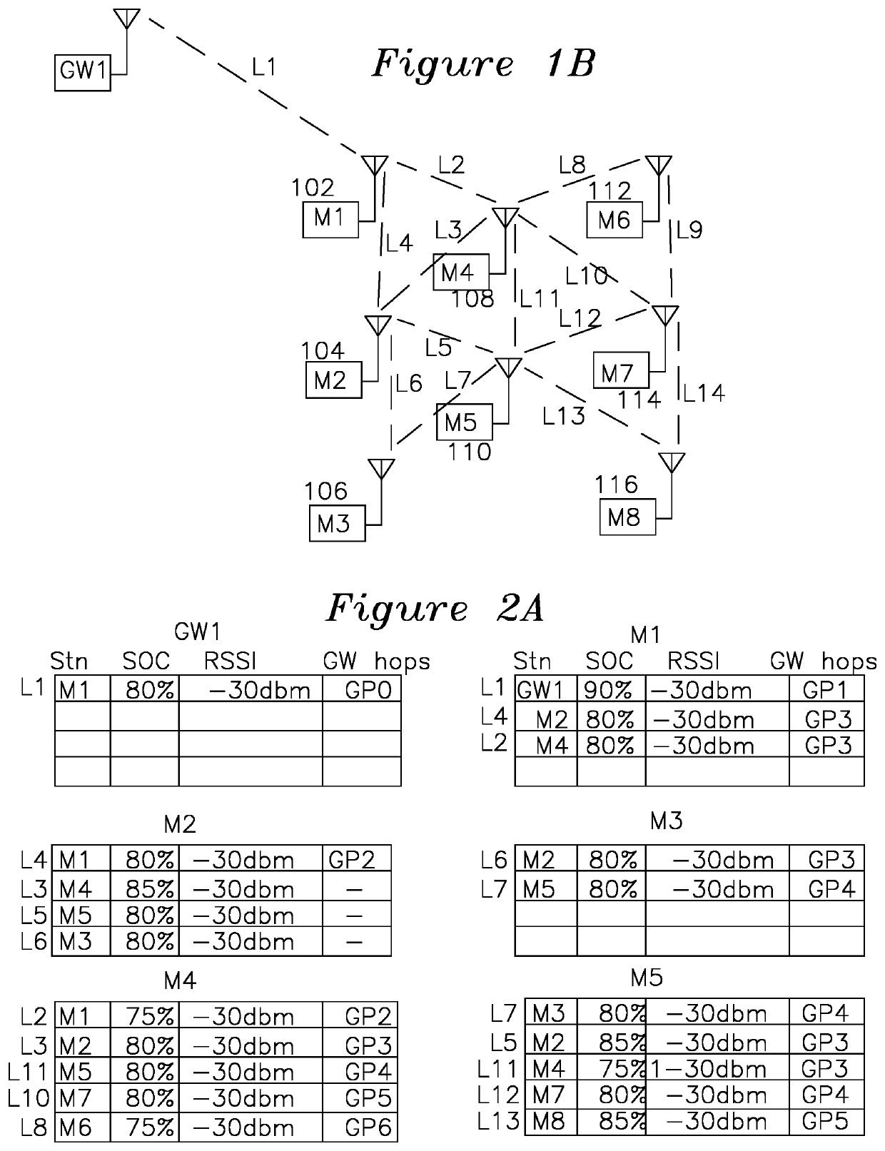
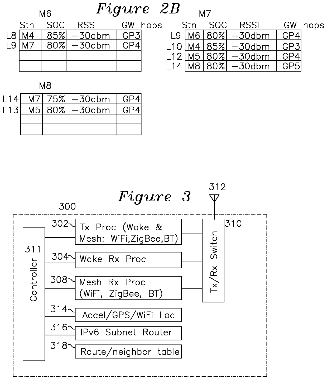
[0046]FIG. 1B shows an example mesh network formed from mesh devices of the present invention. Each of the mesh stations M1102, M2104, M3106, M4108, M5110, M6112, M7114, M8116 is shown as 300 of FIG. 3, which includes wakeup receive processor 304 for waking up the mesh receive processor 308 from an RF sequence, and transmit processor 302, which is operative in a wakeup transmit mode for sending a wakeup sequence formed from keyed RF patterns (or alternatively from entire WLAN packets) as a sequence of “1” values for an entire packet or RF duration or “0” when not transmitting for an equal interval of time, sending this sequence to surrounding mesh stations as RF. In a mesh transmit mode, the transmit processor 302 may transmit ACK and data packets as IEEE 802.11ac, IEEE 802.11n, IEEE 802.11g, or any IEEE 802.11 frame format, or it may transmit ACK and data packets as Zigbee, or it may transmit ack and data packets as Bluetooth packets, either as BLE or BLR packets.

[0047]Each station...


PUM


Abstract

A mesh receiver has a wakeup receiver for reception of a wakeup sequence formed by keyed RF or a sequence of wireless packets and gaps, a transmitter forming low speed RF wakeup sequence to other mesh stations, a mesh receiver for reception of high speed WLAN packets, the transmitter sending a wireless ACK packet in response to a wakeup sequence, the mesh receiver thereafter receiving wireless packets from a remote station, the mesh transmitter sending an ACK, the mesh station thereafter identifying a next hop station, and sending a wakeup sequence to that station, after receipt of an ACK, sending the data, the mesh receiver and mesh transmitter thereafter going to sleep.

Description

FIELD OF THE INVENTION[0001]The present invention relates to stations and methods for providing low power connectivity in a mesh network. In particular, the invention provides ultra-low power connectivity for stations positioned in receiving range of each other.BACKGROUND OF THE INVENTION[0002]Prior art wireless systems such as 802.11 provide communications where a central node (an “access point”) is coupled to other stations using an “infrastructure mode”. This type of infrastructure system relies on the access point being powered continuously, and the power savings comes about by using, for example, access point beacon frames, where the access point periodically transmits beacon frames at expected times, such that the stations wake up at corresponding intervals of time and listen to beacon TDIM frames which indicate whether packets are available at that time of coming out of a sleep mode. The power consumption is thereby reduced by a factor equal to the small percentage of time th...

Claims


Application Information

Patent Timeline
Patent Type & Authority Patents(United States)
IPC IPC(8): H04L12/12H04W84/18H04W4/80H04W84/12
CPCH04L12/12H04W84/18H04W84/12H04W4/80Y02D30/70
Inventor MURALI, PARTHA SARATHYMANTHA, AJAYANAKALA, NAGARAJ REDDYKALLAM, SUBBA REDDYMATTELA, VENKAT
Owner SILICON LAB INC
Why Eureka
Try Eureka