Dehydrogenation catalyst

a technology of dehydrogenation catalyst and catalyst, which is applied in the direction of physical/chemical process catalyst, metal/metal-oxide/metal-hydroxide catalyst, bulk chemical production, etc., to achieve the effect of improving the yield of an olefin and preventing or reducing coking

Pending Publication Date: 2021-11-11
KUBOTA LTD
View PDF0 Cites 0 Cited by
  • Summary
  • Abstract
  • Description
  • Claims
  • Application Information

AI Technical Summary

Benefits of technology

[0012]An aspect of the present invention brings about the effect of providing a dehydrogenating catalyst that is capable of preventing or reducing coking and improving the yield of an olefin in a pyrolysis reaction of a hydrocarbon raw material.

Problems solved by technology

Moreover, the process of pyrolysis of a hydrocarbon as a raw material has various problems such as deposition of carbon (coke) (such a deposition is “coking”) on an inner surface of the pyrolysis tube and a carburization phenomenon that occurs on the inner surface of the pyrolysis tube.

Method used


Image

  • Dehydrogenation catalyst
  • Dehydrogenation catalyst
  • Dehydrogenation catalyst

Examples


embodiment 1

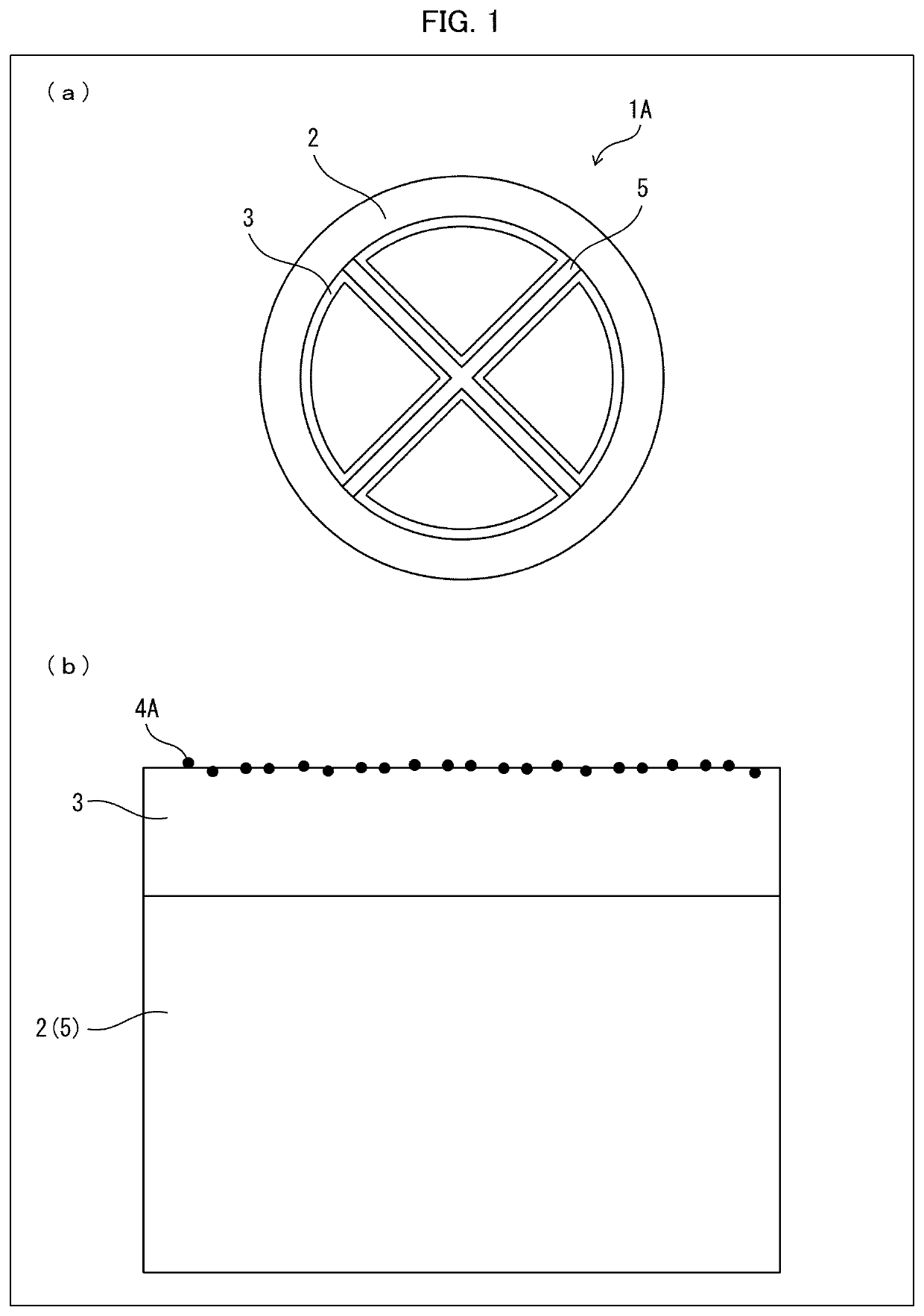
[0020]The following description will discuss details of a pyrolysis tube 1A for production of an olefin in accordance with Embodiment 1 of the present invention with reference to FIG. 1. FIG. 1 illustrates a configuration of the pyrolysis tube 1A in accordance with Embodiment 1, in which (a) of FIG. 1 is a cross-sectional view schematically illustrating the pyrolysis tube 1A, and (b) of FIG. 1 is an enlarged view illustrating an inner surface of the pyrolysis tube 1A illustrated in (a) of FIG. 1.

[0021]As illustrated in (a) and (b) of FIG. 1, the pyrolysis tube 1A in accordance with Embodiment 1 includes: a tubular base material 2 made of a heat resistant metal material; a plate-shaped member (insert material) 5 made of a heat resistant metal material; an alumina layer 3 which is a metal oxide layer containing Al2O3 and which is provided on an inner surface of the tubular base material 2 and on surfaces of the plate-shaped member (insert material) 5; and particles of a dehydrogenatin...

modification example

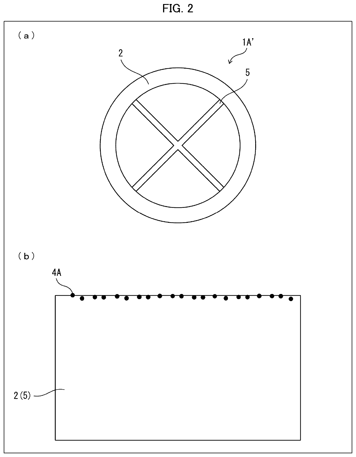
[0080]The following description will discuss a pyrolysis tube 1A′, which is a modification example of the pyrolysis tube 1A in Embodiment 1, with reference to FIG. 2. FIG. 2 illustrates a configuration of the pyrolysis tube 1A′, in which (a) of FIG. 2 is a cross-sectional view schematically illustrating the pyrolysis tube 1A′, and (b) of FIG. 2 is an enlarged view illustrating an inner surface of the pyrolysis tube 1A′ illustrated in (a) of FIG. 2.

[0081]The pyrolysis tube 1A in accordance with Embodiment 1 is configured such that the alumina layer 3 which is a metal oxide layer containing Al2O3 is provided on the inner surface of the base material 2 and the surfaces of the plate-shaped member 5 and that the dehydrogenating catalyst 4A is supported on the surface of the alumina layer 3. The pyrolysis tube 1A′, which is a modification example, is different from the pyrolysis tube 1A in that the dehydrogenating catalyst 4A is directly supported on the inner surface of the tubular base ...

embodiment 2

[0084]The following description will discuss another embodiment of the present invention. For convenience of explanation, the same reference numerals are given to constituent members which have functions identical with those described in Embodiment 1, and descriptions regarding such constituent members are omitted.

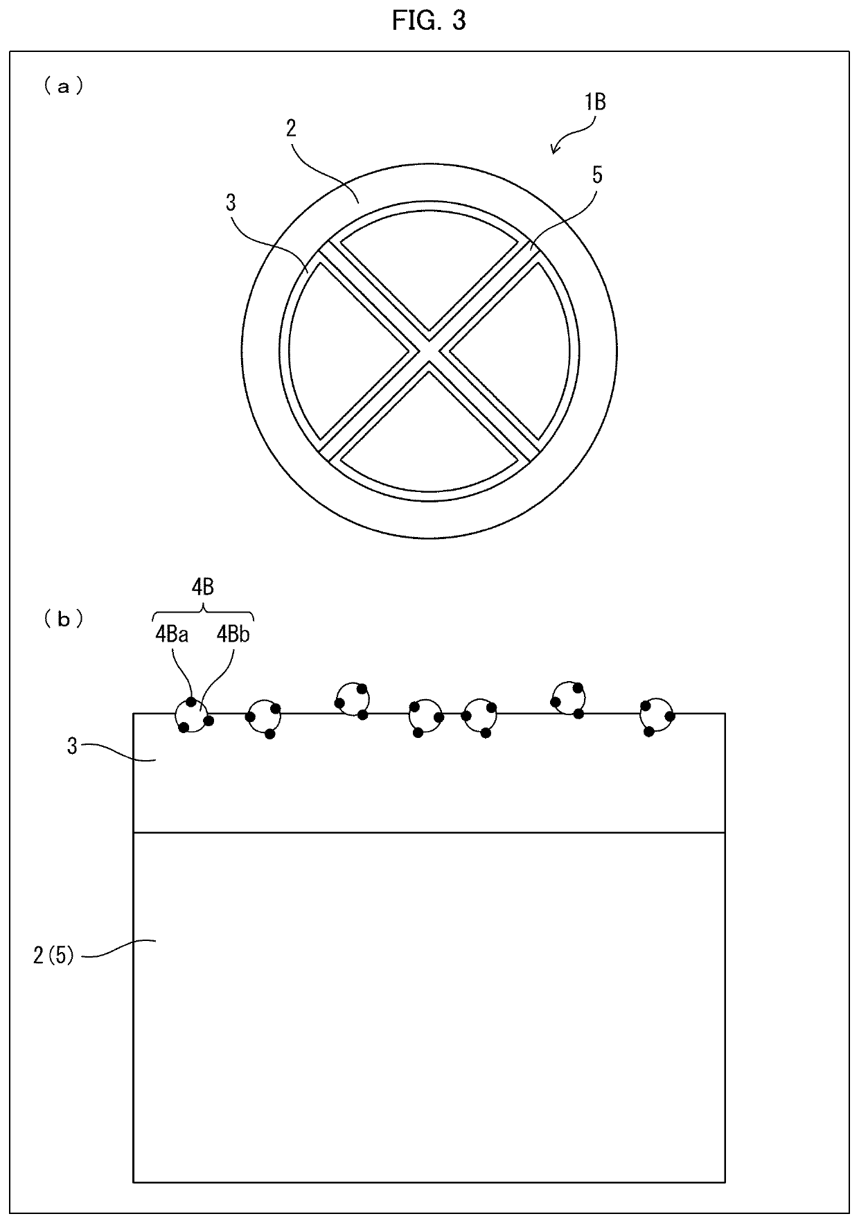
[0085]In a pyrolysis tube 1B for production of an olefin in accordance with Embodiment 2, a dehydrogenating catalyst has a configuration different from that of the dehydrogenating catalyst 4A in Embodiment 1.

[0086](Dehydrogenating Catalyst 4B)

[0087]The following description will discuss details of the pyrolysis tube 1B in accordance with Embodiment 2 of the present invention with reference to FIG. 3. FIG. 3 illustrates a configuration of the pyrolysis tube 1B in accordance with Embodiment 2, in which (a) of FIG. 3 is a cross-sectional view schematically illustrating the pyrolysis tube 1B, and (b) of FIG. 3 is an enlarged view illustrating an inner surface of the pyrolysis ...


PUM

PropertyMeasurementUnit
specific surface areaaaaaaaaaaa
crystallite sizeaaaaaaaaaa
temperatureaaaaaaaaaa

Abstract

Provided is a dehydrogenating catalyst that is capable of preventing or reducing coking and improving the yield of an olefin in a pyrolysis reaction of a hydrocarbon raw material. A dehydrogenating catalyst (4A) for production of an olefin contains, as a catalyst component, at least one of La and Ce, wherein, when the dehydrogenating catalyst (4A) does not contain Ce, the dehydrogenating catalyst (4A) contains at least one element selected from the group consisting of Ba, Fe, and Mn, or wherein, when the dehydrogenating catalyst (4A) contains Ce, the dehydrogenating catalyst (4A) contains at least one of Fe and Mn.

Description

TECHNICAL FIELD[0001]The present invention relates to a dehydrogenating catalyst.BACKGROUND ART[0002]Olefins such as ethylene and propylene are used to manufacture chemical synthetic products for various purposes of use in industries. An olefin is produced by supplying a petroleum-derived hydrocarbon such as ethane or naphtha into a pyrolysis tube (cracking tube), and pyrolyzing the hydrocarbon in a gas phase by heating at 700° C. to 900° C. In the production method, a large amount of energy is required to achieve high temperature. Moreover, the process of pyrolysis of a hydrocarbon as a raw material has various problems such as deposition of carbon (coke) (such a deposition is “coking”) on an inner surface of the pyrolysis tube and a carburization phenomenon that occurs on the inner surface of the pyrolysis tube. Under the circumstances, development of a high-performance dehydrogenating catalyst that can solve those problems is demanded.[0003]For example, Patent Literature 1 disclo...

Claims


Application Information

Patent Timeline
Patent Type & Authority Applications(United States)
IPC IPC(8): B01J23/745B01J35/10B01J35/00C07C5/32B01J21/04B01J23/889B01J23/34B01J23/00B01J23/10
CPCB01J23/745B01J35/1009B01J35/1014B01J35/006B01J23/10B01J21/04B01J23/8892B01J23/34B01J23/002C07C5/322Y02P20/52C07C5/3332C07C2523/34C07C2523/83C07C2523/889B01J2523/00B01J37/0215C07C11/04B01J2523/25B01J2523/3706B01J2523/72B01J2523/842
Inventor MAEDA, SHUNHASHIMOTO, KUNIHIDESEKINE, YASUSHI
Owner KUBOTA LTD
Why Eureka
Try Eureka