
Assisted exoskeleton rehabilitation device

a rehabilitation device and exoskeleton technology, applied in the field of biomimetic machinery, can solve the problems of low power/mass ratio, poor flexibility, high cost, etc., and achieve the effects of high power density ratio, high safety, and simple structur

Active Publication Date: 2021-11-18
BEIJING BOE OPTOELECTRONCIS TECH CO LTD +1
View PDF0 Cites 1 Cited by
  • Summary
  • Abstract
  • Description
  • Claims
  • Application Information

AI Technical Summary

Benefits of technology

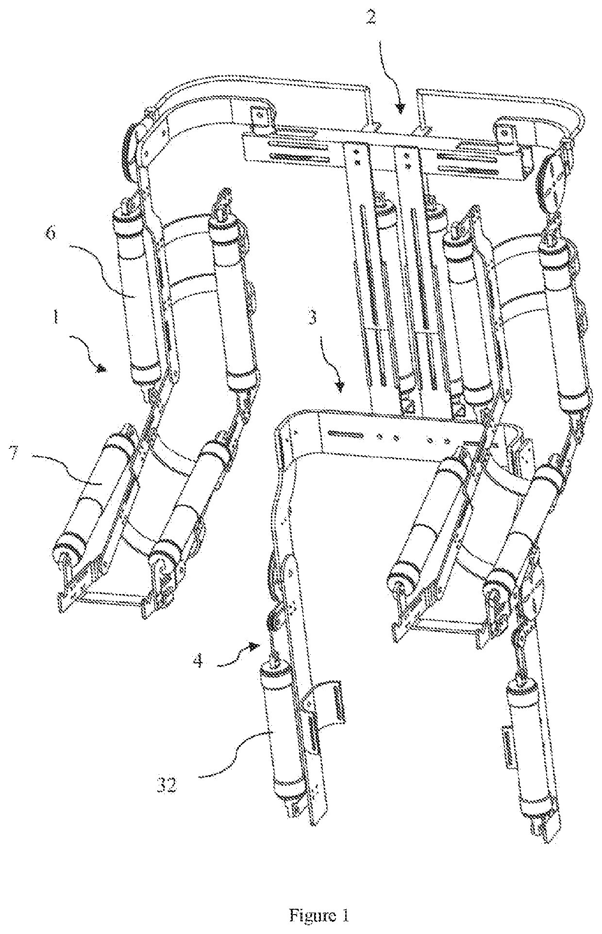
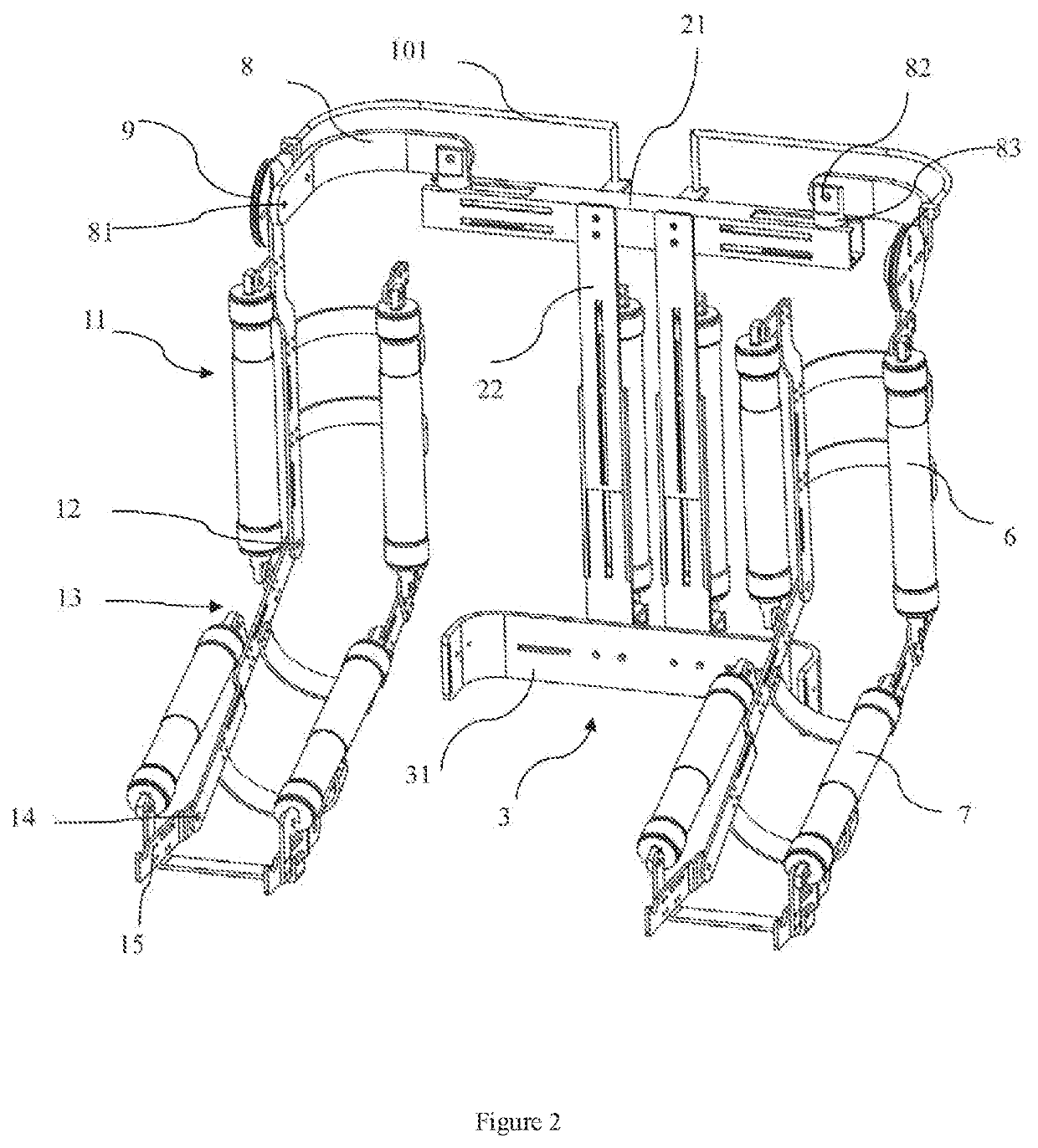
The present invention provides an assisted exoskeleton rehabilitation device with the advantages of simplicity, safety, and flexibility. The device has multiple degrees of freedom, including bend-stretch degrees of freedom for the shoulder joints, elbow joint, and wrist joint, as well as a slideable back structure for adjusting the waist position. The device allows the wearer to make bending and standing movements while lifting heavy objects. It can be used in fields such as rehabilitation treatment, family service, disaster relief, and material transfer.

Problems solved by technology

This traditional driving method has the disadvantages of high cost, low power / mass ratio, oil leakage, and poor flexibility.
Consequently, the exoskeleton product is too heavy to meet the requirements of portability and flexibility.
Moreover, the price of exoskeleton product is high, such that it cannot be used widely.

Method used


Image

  • Assisted exoskeleton rehabilitation device
  • Assisted exoskeleton rehabilitation device
  • Assisted exoskeleton rehabilitation device

Examples


Embodiment Construction

[0030]The embodiments of the present disclosure will be illustrated in detail below, examples of which are shown in the drawings, wherein the same or like reference numerals will be used to refer to the same or like elements or elements with the same or similar functions. The embodiments described below with reference to the accompanying drawings are exemplary only, and shall be only for the purpose of interpreting but not for limiting the present disclosure.

[0031]Firstly, the technical principle of the pneumatic muscle element is explained. FIG. 10 is a schematic view of a pneumatic muscle element according to the present disclosure. The pneumatic muscle element is a new type of driver, and its main body is a rubber tube D. An outer side of the rubber tube is covered with a woven mesh C made of PET material. Two ends of the rubber tube D are sleeved on sealing plugs E, F disposed at both ends thereof. The sealing plug F at one end is not provided with an air hole, but completely bl...


PUM


Abstract

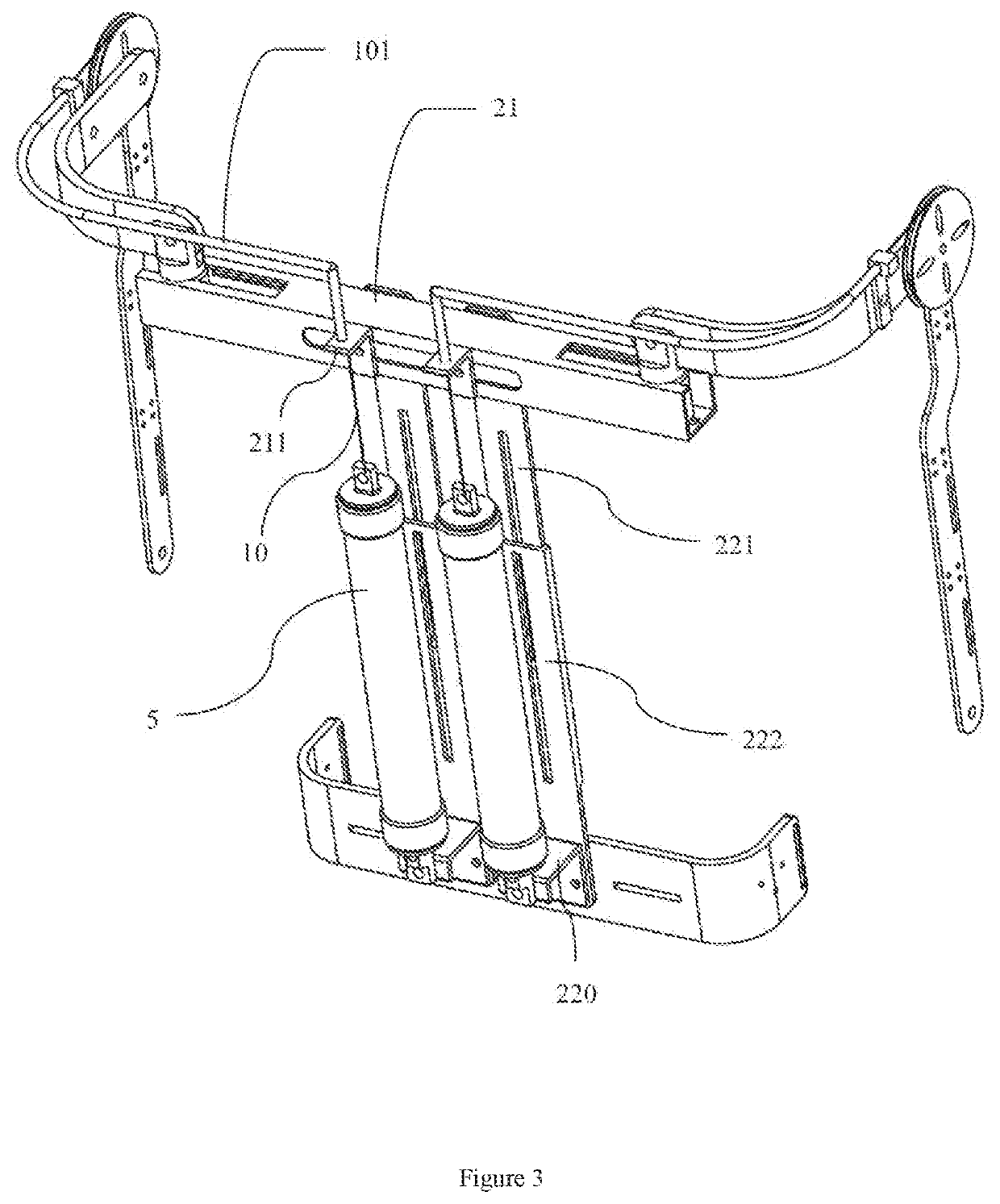
The present disclosure relates to an assisted exoskeleton rehabilitation device, comprising: a back structure comprising a back crossbeam, a back supporting panel with an adjustable length, and a shoulder pneumatic muscle element mounted on the back supporting panel; an arm structure; a shoulder joint assembly, by which the arm structure is connected to an upper end of the back structure; and a waist structure. An upper end of the back supporting panel is fixedly connected to the back crossbeam, and a lower end thereof is fixedly connected to the waist structure. The shoulder joint assembly comprises a curved shoulder joint connecting panel, a shoulder traction wheel, a shoulder traction line, a first hinge mechanism and a second hinge mechanism. One end of the shoulder joint connecting panel is connected to the upper end of the arm structure by the first hinge mechanism to form a bend-stretch revolute pair of the shoulder joint, and the other end of the shoulder joint connecting panel is connected to the back crossbeam by the second hinge mechanism to form an abduction-adduction revolute pair and a medial rotation-lateral rotation revolute pair of the shoulder joint assembly, and the shoulder traction wheel is fixed to the upper end of the arm structure. The shoulder traction line is connected at one end to the shoulder traction wheel, and connected to the shoulder pneumatic muscle element at the other end.

Description

CROSS REFERENCE TO RELATED APPLICATIONS[0001]This patent application is a National Stage Entry of PCT / CN2019 / 073702 filed on Jan. 29, 2019, which claims the benefit and priority of Chinese Patent Application No. 201810272761.0 filed on Mar. 29, 2018, the disclosures of which are incorporated by reference herein in their entirety as part of the present application.BACKGROUND[0002]Embodiments of the present disclosure relate to the field of biomimetic machinery, and in particular, to an assisted exoskeleton rehabilitation device driven by pneumatic muscles.[0003]In modern society, it is necessary to develop an assisted exoskeleton device to provide limbs and body support services for care workers when they carrying the elderly or patients. This can greatly reduce the physical labor intensity of the care workers while ensuring the safety of both patients and care workers, so that the care workers can work in an easy and efficient manner. For the elderly with degenerative muscle functio...

Claims


Application Information

Patent Timeline
Patent Type & Authority Applications(United States)
IPC IPC(8): A61H1/02B25J9/00
CPCA61H1/0281A61H1/0277A61H1/0292A61H2201/165B25J9/0006A61H2201/5056A61H2201/1642A61H1/0244A61H1/0218A61H1/0274A61H1/0285A61H2201/1638A61H2201/1623A61H2201/1238
Inventor XUE, BANGCANLIU, YANJUN
Owner BEIJING BOE OPTOELECTRONCIS TECH CO LTD
Learn More