
Shear Wave Elastography with Ultrasound Probe Oscillation

a technology of ultrasound probe and elastography, which is applied in the field of shear wave elastography with ultrasound probe oscillation, can solve the problems of depth dependent probe motion artifact, limited elastography technique, and inability to image a large 2d area

Active Publication Date: 2021-11-18
MAYO FOUND FOR MEDICAL EDUCATION & RES
View PDF11 Cites 2 Cited by
  • Summary
  • Abstract
  • Description
  • Claims
  • Application Information

AI Technical Summary

Benefits of technology

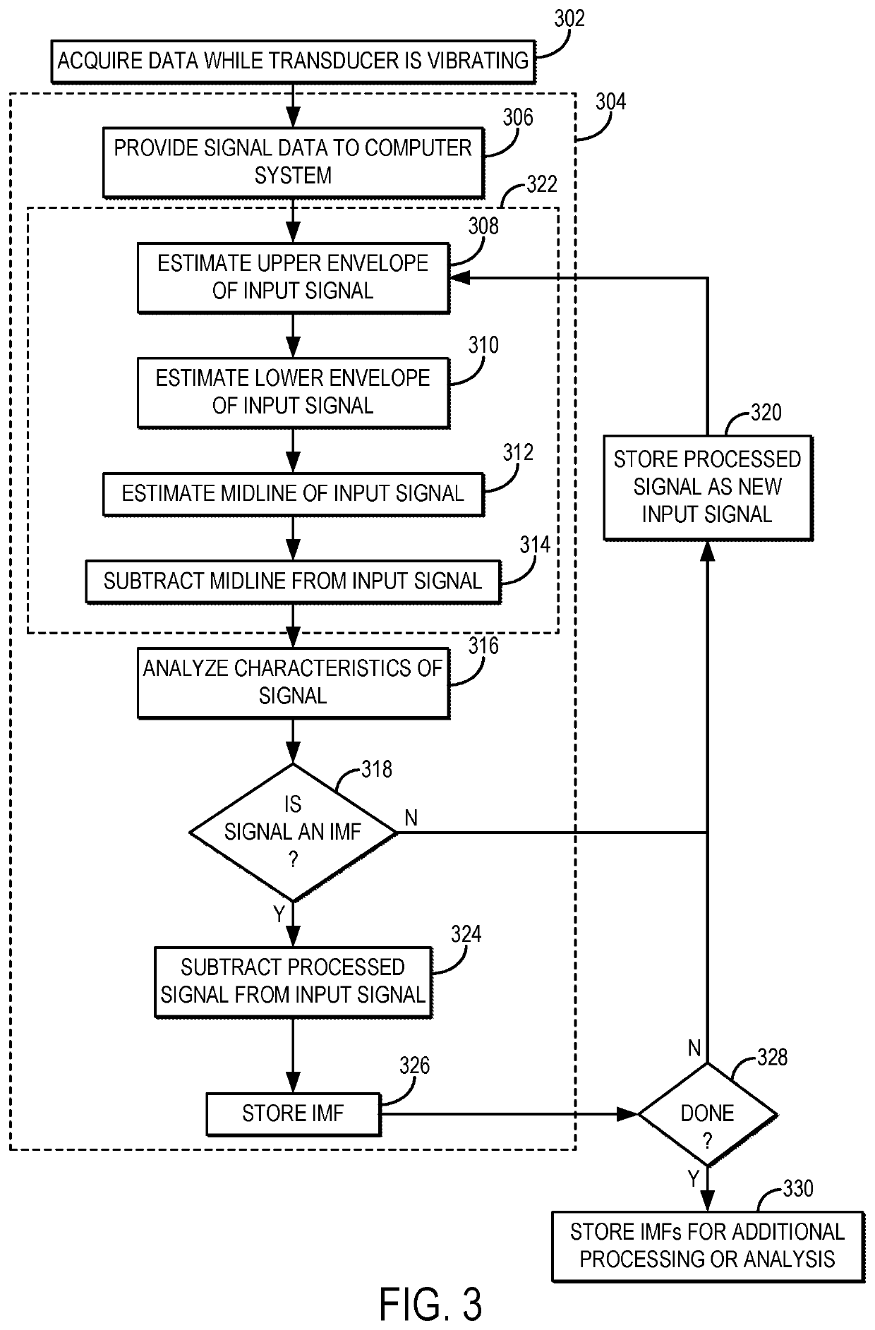
The present invention provides a method for ultrasound elastography that uses a continuously vibrated ultrasound transducer to induce a shear wave in an object and acquire signal data from the object using the ultrasound transducer. The signal data is processed using an empirical mode decomposition to extract an intrinsic mode function (IMF) that represents motion of the shear wave in the object that has been separated from probe motion artifacts associated with the vibration. The IMF is then stored as shear wave signal data for later processing or use. This method improves the accuracy of ultrasound elastography and enhances the ability to diagnose and treat diseases such as breast cancer.

Problems solved by technology

While versatile, the ARF technique is limited by ultrasound attenuation and shear wave attenuation.
Even at shallower depths, the resulting shear wave rapidly attenuates, preventing the method from imaging a large 2D area.
Another constraint is that scanners must be equipped with specialized hardware and power supplies to generate the high intensity, long duration push pulses, and imaging frame-rates are typically limited to about 1 Hz to prevent excess tissue and probe thermal damage.
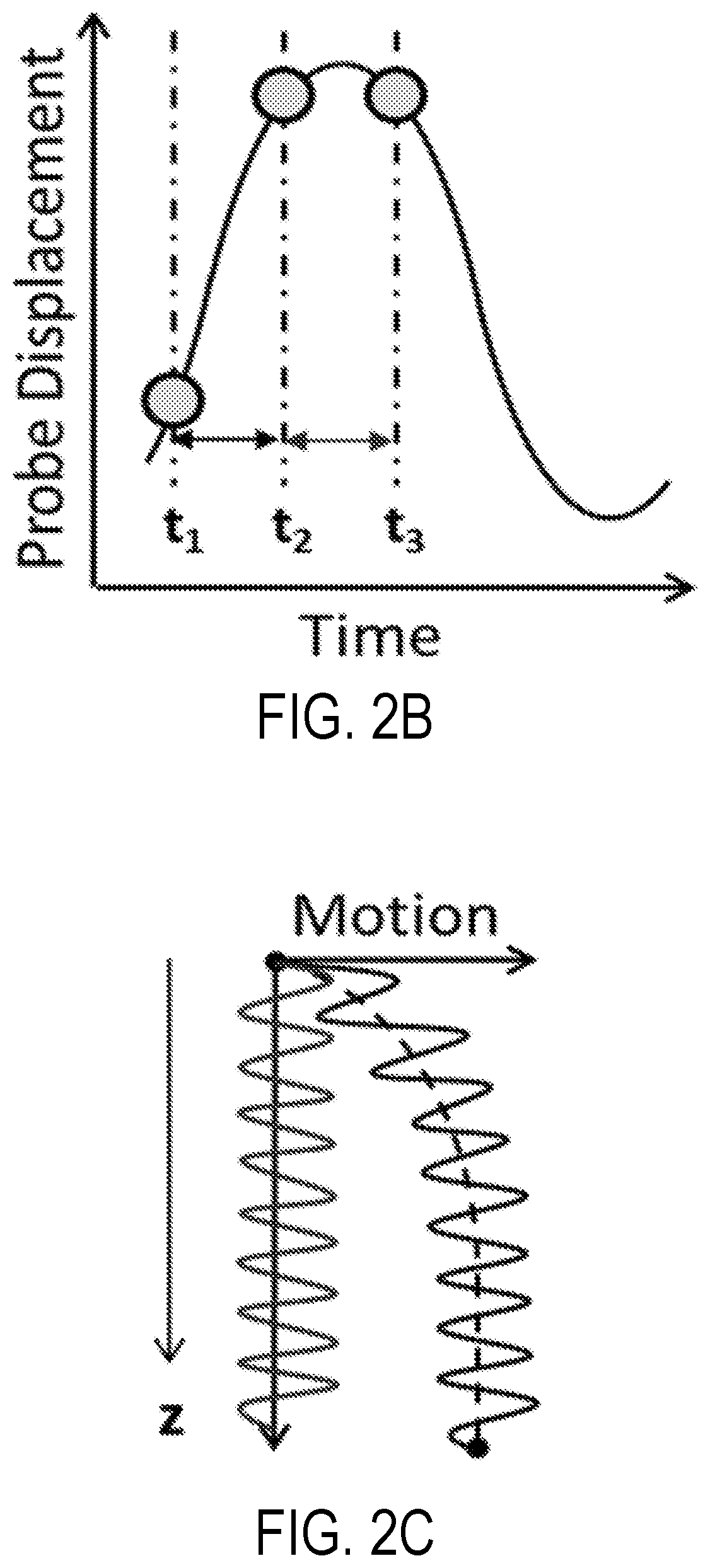
Because ultrasound utilizes changes in individual scatterer positions relative to the ultrasound transducer to track motion, the movement of the vibrating transducer between subsequent detections leads to a depth dependent probe motion artifact.
This results in a non-linear strain-like artifact, causing a bias in shear wave speed estimates.

Method used


Image

  • Shear Wave Elastography with Ultrasound Probe Oscillation
  • Shear Wave Elastography with Ultrasound Probe Oscillation
  • Shear Wave Elastography with Ultrasound Probe Oscillation

Examples


Embodiment Construction

[0017]Described here are systems and methods for processing data acquired using ultrasound elastography, in which shear waves are generated in a subject using continuous vibration of the ultrasound transducer. The systems and methods described here can effectively remove signals corresponding to residual motion artifacts associated with vibration of the ultrasound transducer. The systems and methods described here also provide for real-time visualization of shear waves propagating in the subject.

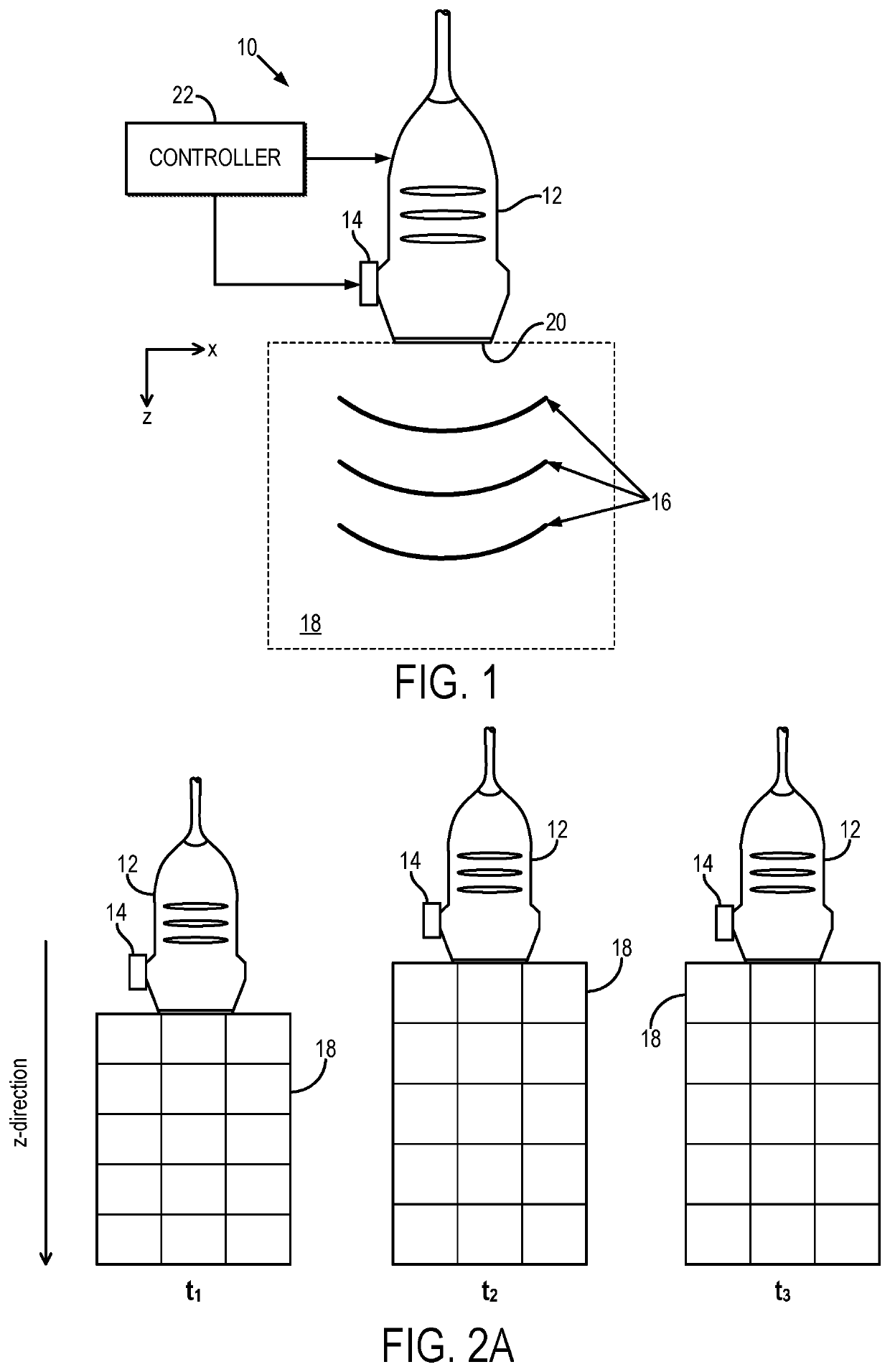
[0018]Referring first to FIG. 1, an example system 10 for inducing shear waves in an object 20 is illustrated. In this system, the transducer 12 is mechanically vibrated by an actuator 14, which causes the transducer 12 to oscillate in the axial direction (e.g., the z-direction in FIG. 1). As one example, the actuator 14 can be a mechanical actuator, such as a voice coil actuator. As the transducer 12 moves in the axial direction, shear waves 16 are induced within the object 18. Shear waves ...


PUM


Abstract

Methods for processing data acquired using ultrasound elastography, in which shear waves are generated in a subject using continuous vibration of the ultrasound transducer, are described. The described methods can effectively separate shear wave signals from signals corresponding to residual motion artifacts associated with vibration of the ultrasound transducer. The systems and methods described here also provide for real-time visualization of shear waves propagating in the subject.

Description

CROSS-REFERENCE TO RELATED APPLICATIONS[0001]This application claims the benefit of U.S. Provisional Patent Application Ser. No. 62 / 543,698, filed on Aug. 10, 2017, and entitled “SHEAR WAVE ELASTOGRAPHY WITH ULTRASOUND PROBE OSCILLATION,” which is herein incorporated by reference in its entirety.STATEMENT REGARDING FEDERALLY SPONSORED RESEARCH[0002]This invention was made with government support under DK106957 awarded by the National Institutes of Health. The government has certain rights in the invention.BACKGROUND[0003]Many ultrasound elastography techniques have been developed, which are capable of obtaining measurements of mechanical properties in an object or tissue, such as in the liver. These methods utilize shear wave propagation speed to quantitatively estimate the stiffness of soft tissue or other materials. For example, for an elastic material, the shear modulus is equal to the square of the shear wave speed times its density (often assumed to be 1000 kg / m3 for soft tissu...

Claims


Application Information

Patent Timeline
IPC IPC(8): G01N29/04G01N29/07G01N29/46G01N29/06G01N29/34G01N29/42
CPCG01N29/043G01N29/07G01N29/46G01N29/0645G01N2291/044G01N29/42G01N2291/106G01N2291/0422G01N2291/02475G01N29/348A61B8/485A61B8/5276G01N29/069
Inventor CHEN, SHIGAOGREENLEAF, JAMES F.MANDUCA, ARMANDOMELLEMA, DANIEL C.TRZASKO, JOSHUA D.URBAN, MATTHEW W.
Owner MAYO FOUND FOR MEDICAL EDUCATION & RES
Learn More