Unlock instant, AI-driven research and patent intelligence for your innovation.

Automatic adjusting method for equipment and smart adjusting device using the same

Active Publication Date: 2021-11-18
UNITED MICROELECTRONICS CORP
View PDF0 Cites 1 Cited by
  • Summary
  • Abstract
  • Description
  • Claims
  • Application Information

AI Technical Summary

Benefits of technology

The invention is about a method and device for automatically adjusting equipment using a software robot called Robotic Process Automation (RPA). The method involves analyzing pixel variations in a template frame and comparing it with clear frames to calculate an offset. The offset is then used to adjust a parameter of the equipment to reduce the statistical value. The device includes a communication unit for remote connection, a frame analyzing unit with a template frame analyzer, clarity analyzer, offset calculator, and statistical analyzer, and a remote controlling unit with an adjuster. The technical effect of the invention is to automate the adjustment process for equipment, making it faster and more efficient.

Problems solved by technology

With the development of semiconductor technology, the operation of measuring equipment and process equipment is becoming more and more complex.
Each measuring equipment and process equipment needs an operator to monitor at any time, so it must consume a lot of manpower to operate the measuring equipment and process equipment.
Especially in scanning electron microscopes and lithography equipment, the screen may flicker and shake.
However, software robots' ability to recognize the stability of the frame is quite inadequate, and there is a considerable degree of difficulty, which has been formed a technical bottleneck for a long time.

Method used


Image

  • Automatic adjusting method for equipment and smart adjusting device using the same
  • Automatic adjusting method for equipment and smart adjusting device using the same
  • Automatic adjusting method for equipment and smart adjusting device using the same

Examples


Embodiment Construction

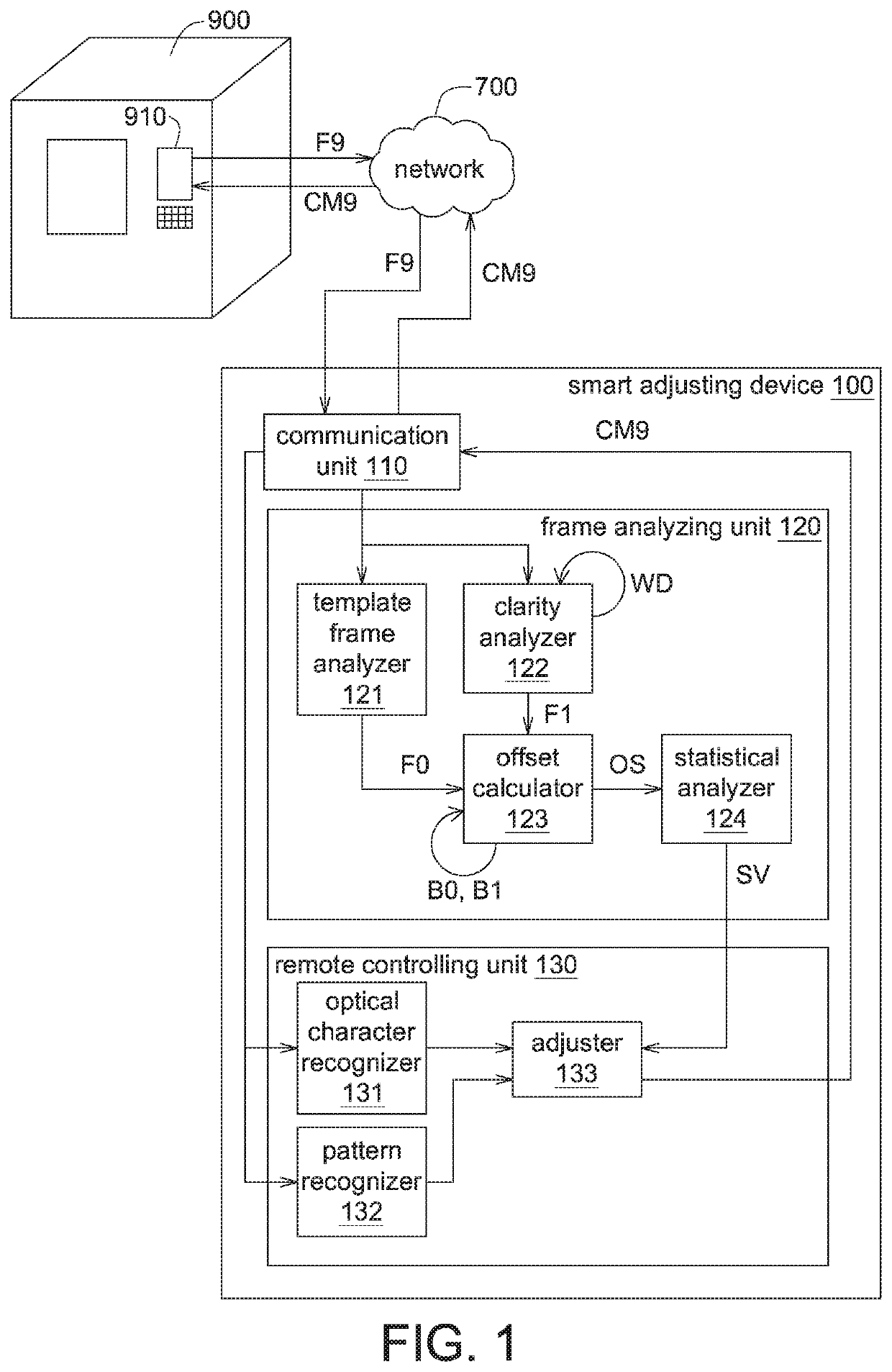
[0019]Please refer to FIG. 1, which shows a smart adjusting device 100 according to one embodiment. For example, a smart adjusting device 100 is a server, a cluster computing system, or a computer. The smart adjusting device 100 is configured to control the equipment 900. The equipment 900 may be a process equipment or a measuring equipment, such as a Critical Dimension Scanning Electron Microscope (CD-SEM). The equipment 900 has a user interface 910. The user interface 910 may be a touch screen. The operator may click the command block on the operation frame F9 shown on the user interface 910, to give an adjusting command CM9 to the equipment 900. In the present embodiment, the smart adjusting device 100 can analyze the operation frame F9 remotely, and give the adjusting command CM9 according to the analysis result, without the need for the operator to stand in front of the equipment 900.

[0020]Please referring to FIG. 1, a smart adjusting device 100 includes a communication unit 11...


PUM


Abstract

An automatic adjusting method for equipment and a smart adjusting device using the same are provided. The automatic adjusting method of the equipment includes the following steps. A template frame from the equipment is obtained in an initial period. Several clear frames are obtained in one window period. Each of the template frame and the clear frame has a pixel variation. The pixel variation of the template frame is the largest in the initial period. The pixel variation of each of the clear frame is greater than a threshold. Each of the clear frame is compared with the template frame to obtain an offset. A statistical value of the offsets is calculated. A parameter of the equipment is adjusted to reduce the statistical value.

Description

[0001]This application claims the benefit of People's Republic of China application Serial No. 202010418228.8, filed May 18, 2020, the subject matter of which is incorporated herein by reference.BACKGROUND OF THE INVENTIONField of the Invention[0002]The invention relates in general to an automatic controlling method and an electric device using the same, and more particularly to an automatic adjusting method for equipment and a smart adjusting device using the same.Description of the Related Art[0003]With the development of semiconductor technology, the operation of measuring equipment and process equipment is becoming more and more complex. During the operation of the measuring equipment and the process equipment, the operator must be quite familiar with the user interface process. According to the information displayed on the screen, the operator performs the corresponding operations. Each measuring equipment and process equipment needs an operator to monitor at any time, so it mu...

Claims


Application Information

Patent Timeline
IPC IPC(8): G06T1/00G06T7/20G06T7/00
CPCG06T1/0014G06T7/20G06T2207/10061G06T2200/24G06T2207/30148G06T7/0004G05B19/04G05B19/0426G06V30/14G09G2320/0247G09G2380/00G09G3/006G09G2354/00
Inventor LIN, YU-CHIYANG, LI-HSINLIN, CHING-PEICHEN, MING-WEIZHU, WEI-HONG
Owner UNITED MICROELECTRONICS CORP
Features
  • R&D
  • Intellectual Property
  • Life Sciences
  • Materials
  • Tech Scout
  • Unparalleled Data Quality
  • Higher Quality Content
  • 60% Fewer Hallucinations
Learn More