Secondary battery

a second battery and battery technology, applied in the field of secondary batteries, can solve the problems of reducing size, energy density, and insufficient effect, and achieve the effects of reducing size and weight, resisting components, and high heat dissipation

Pending Publication Date: 2021-12-02
HONDA MOTOR CO LTD
View PDF2 Cites 0 Cited by
  • Summary
  • Abstract
  • Description
  • Claims
  • Application Information

AI Technical Summary

Benefits of technology

[0014]The secondary battery of the present invention is also applicable to a module configured such that a plurality of secondary batteries is aligned in electrical connection with each other. According to the structure of the collector of the present invention, a bus bar essential for typical module formation is not necessary, and a series design can be achieved by surface contact of both cell surfaces. Thus, a resistance component due to the bus bar can be eliminated, and a low-resistance module design having high heat dissipation can be achieved. Moreover, size and weight reduction can also be achieved.
[0015]In the second battery of the present invention, the conductive base member of the positive / negative electrode is made of foam metal having a three-dimensional structure. The metal foam has the mesh-shaped three-dimensional structure, and has a large surface area. The foam porous body made of the metal is used as the conductive base member of the positive / negative electrode so that the mesh-shaped structure can be filled with an electrode compounding agent containing an electrode active material and an active material amount per unit area of an electrode layer can be increased. In addition, the volumetric energy density of the lithium ion secondary battery can be improved.
[0016]Since the collection tab is not necessary, the present invention can prevent, as additional effects, durability deterioration due to uneven welding at a step welded portion between the collection tab and the exterior body (a laminated film), can reduce liquid leakage and gas leakage due to such durability deterioration, and can improve pressure resistance to internal gas.
[0017]Since the collection tab is not necessary, the present invention can eliminate, as other additional effects, the necessity of taking the width of the collection tab into consideration, and can narrow a width between battery cells. Thus, a design can be freely made from one with a small width to one with a great width. The degree of freedom in the design of the shape of the battery cell is increased so that a battery can be produced in a shape corresponding to an application to be applied.
[0018]As described above, the present invention has an advantageous effect that the heat dissipation can be significantly improved because one surface of the collector is formed continuously in the longitudinal direction of the positive / negative electrode, which is configured such that the conductive base member contains the electrode active material, across the large contact area and the other surface of the collector is exposed in the longitudinal direction of the cell structure across the large area. The present invention produces the above-described additional effects.

Problems solved by technology

For this reason, as long as heat dissipation of the collection tab of the collector is not enhanced, even in the structure for reducing accumulated heat in the electrode layer of the battery cell as in Japanese Unexamined Patent Application, Publication No. 2017-212111, such an effect cannot be sufficiently produced.
In a case where the size of the collection tab is increased for improving the heat dissipation of the collection tab, there are problems that an energy density is degraded and an obstacle to size reduction is caused.

Method used


Image

  • Secondary battery
  • Secondary battery
  • Secondary battery

Examples


Embodiment Construction

[0028]Hereinafter, an embodiment of the present invention will be described with reference to the drawings.

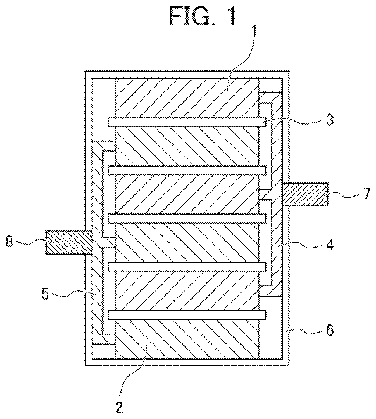
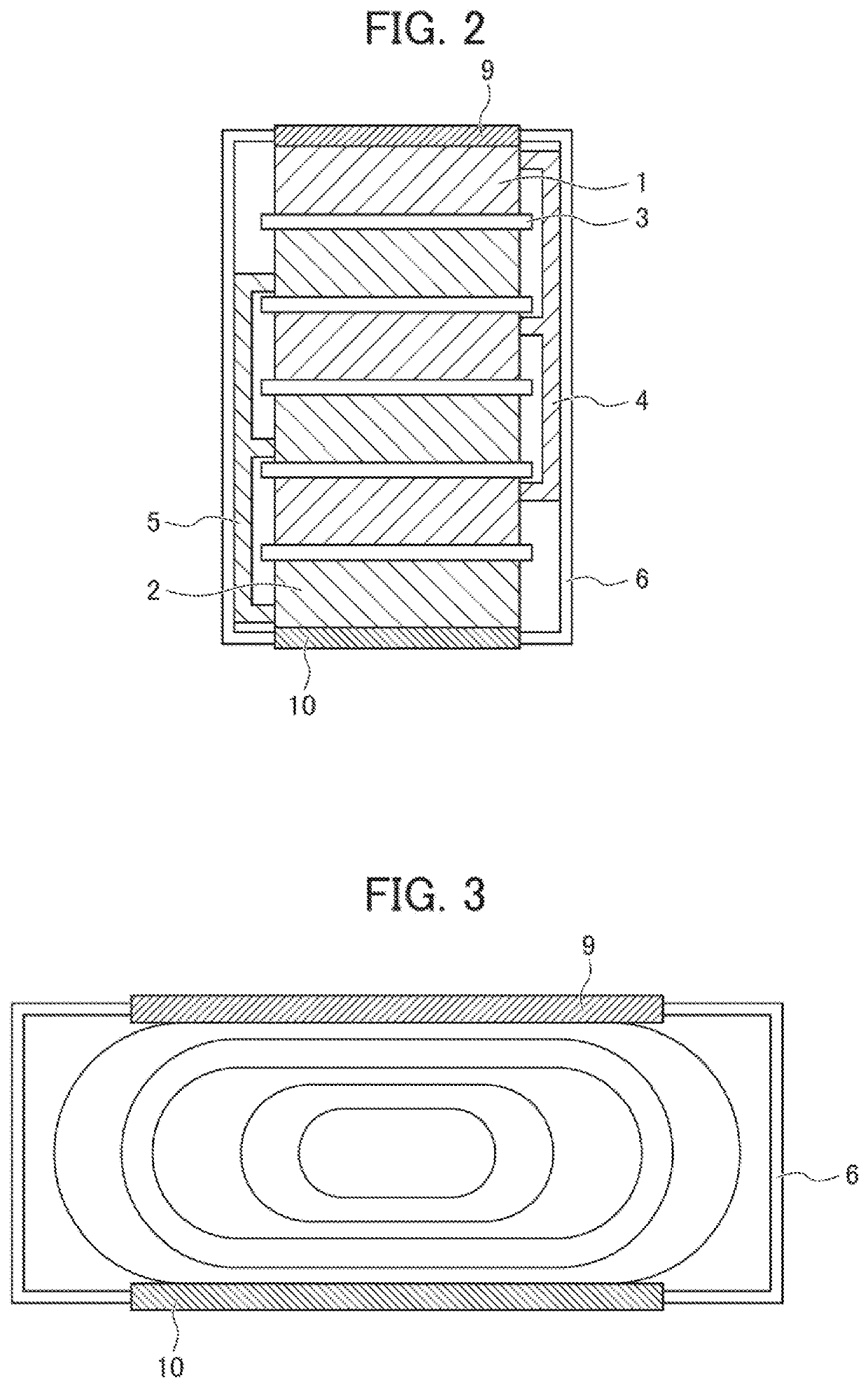
[0029]FIG. 1 shows a cell structure of a battery cell of a typical secondary battery. A reference numeral 1 indicates a positive electrode, a reference numeral 2 indicates a negative electrode, and a reference numeral 3 indicates a separator. The positive electrodes and the negative electrodes are stacked on each other in the order of the positive electrode and the negative electrode from above with each separator being interposed between the positive electrode and the negative electrode. A reference numeral 4 indicates a positive electrode collection member that collects power from each of the stacked positive electrodes, and a reference numeral 5 indicates a negative electrode collection member that collects power from each of the stacked negative electrodes. A reference numeral 6 indicates an exterior body formed of, e.g., a laminated film, and entirely covers the stack of t...


PUM

PropertyMeasurementUnit
pore sizeaaaaaaaaaa
porosityaaaaaaaaaa
particle sizeaaaaaaaaaa

Abstract

To provide a battery cell structure capable of improving heat dissipation without degradation of an energy density and an obstacle to size reduction while an electrode layer of a battery cell has sufficient heat transfer properties. The present invention relates to a cell structure including a positive/negative electrode formed in such a manner that a conductive base member having a three-dimensional structure contains an electrode active material and a collector formed continuously to the positive/negative electrode. One surface of the collector is formed continuously in a longitudinal direction of the positive/negative electrode (across a large area), and the other surface of the collector is exposed in a longitudinal direction of the cell structure (across a large area).

Description

[0001]This application is based on and claims the benefit of priority from Japanese Patent Application 2020-095591 filed on 1 Jun. 2020, the content of which is incorporated herein by reference.BACKGROUND OF THE INVENTIONField of the Invention[0002]The present invention relates to a secondary battery such as a lithium ion battery, and particularly relates to a cell structure of a secondary battery improving heat dissipation in the secondary battery.Related Art[0003]Typically, a lithium ion battery has been widely used as a secondary battery having a high energy density. The secondary battery such as the lithium ion battery includes a cell structure having a collector made of metal foil, a positive / negative electrode configured such that a compounding agent containing an electrode active material is applied to a surface of the collector, and an electrolyte interposed between the positive and negative electrodes.[0004]For developing an effective function and ensuring durability such a...

Claims


Application Information

Patent Timeline
Patent Type & Authority Applications(United States)
IPC IPC(8): H01M10/653H01M10/613H01M4/64H01M10/0525H01M10/654
CPCH01M10/653H01M10/613H01M10/654H01M10/0525H01M4/64H01M4/13H01M10/6551H01M10/6553H01M50/103H01M10/0431H01M10/0562H01M10/0566Y02E60/10Y02P70/50
Inventor TANAAMI, KIYOSHIAOYAGI, SHINTAROISOGAI, YUJI
Owner HONDA MOTOR CO LTD
Why Eureka
Try Eureka