
Enclosed conveyor

a conveyor and enclosed technology, applied in the direction of bearings, shafts and bearings, bearings, etc., can solve the problems of premature wear inconvenience of the return portion, etc., and achieve the effects of reducing the friction between the inner surface of the bottom plate and the return portion of the conveyor belt, reducing the potency, and increasing the potency

Inactive Publication Date: 2021-12-09
TMSA TECH EM MOVIMENTO SA
View PDF0 Cites 1 Cited by
  • Summary
  • Abstract
  • Description
  • Claims
  • Application Information

AI Technical Summary

Benefits of technology

The proposed enclosed conveyor has several technical advantages compared to conventional conveyors. Firstly, it uses an air film to support the return portion of the conveyor belt, reducing friction between the conveyor belt and the inner surface of the bottom plate, allowing for the use of a lower potency traction engine. This results in lower energy consumption and smaller traction pulleys and pre-tension loads. Secondly, the proposed conveyor can be manufactured with a longer length compared to conventional conveyors as there is no need for a large traction engine and its energy consumption to overcome friction along the entire contact area between the conveyor belt and the inner surface of the bottom plate. Lastly, the proposed conveyor uses a horizontal roller to support the conveyor belt, preventing damage to the conveyor belt due to uneven distribution of bulk material.

Problems solved by technology

However, even using a coating to decrease the friction between the return portion of the conveyor belt and the inner surface of the bottom plate of the conventional enclosed conveyor, the use of a traction engine with high potency is still necessary to duly traction said conveyor belt.
However, the alternate enclosed conveyor of the state of the art that uses an air film to support the conveyor belt in the transport portion and the return portion has inconveniences when the bulk material distribution is unequal along the length of said conveyor belt.
Furthermore, the contact of the conveyor belt on the surface where the transport portion moves on might cause a premature wear of said conveyor belt on the points where there is a higher accumulation of bulk material.

Method used


Image

  • Enclosed conveyor
  • Enclosed conveyor
  • Enclosed conveyor

Examples


Embodiment Construction

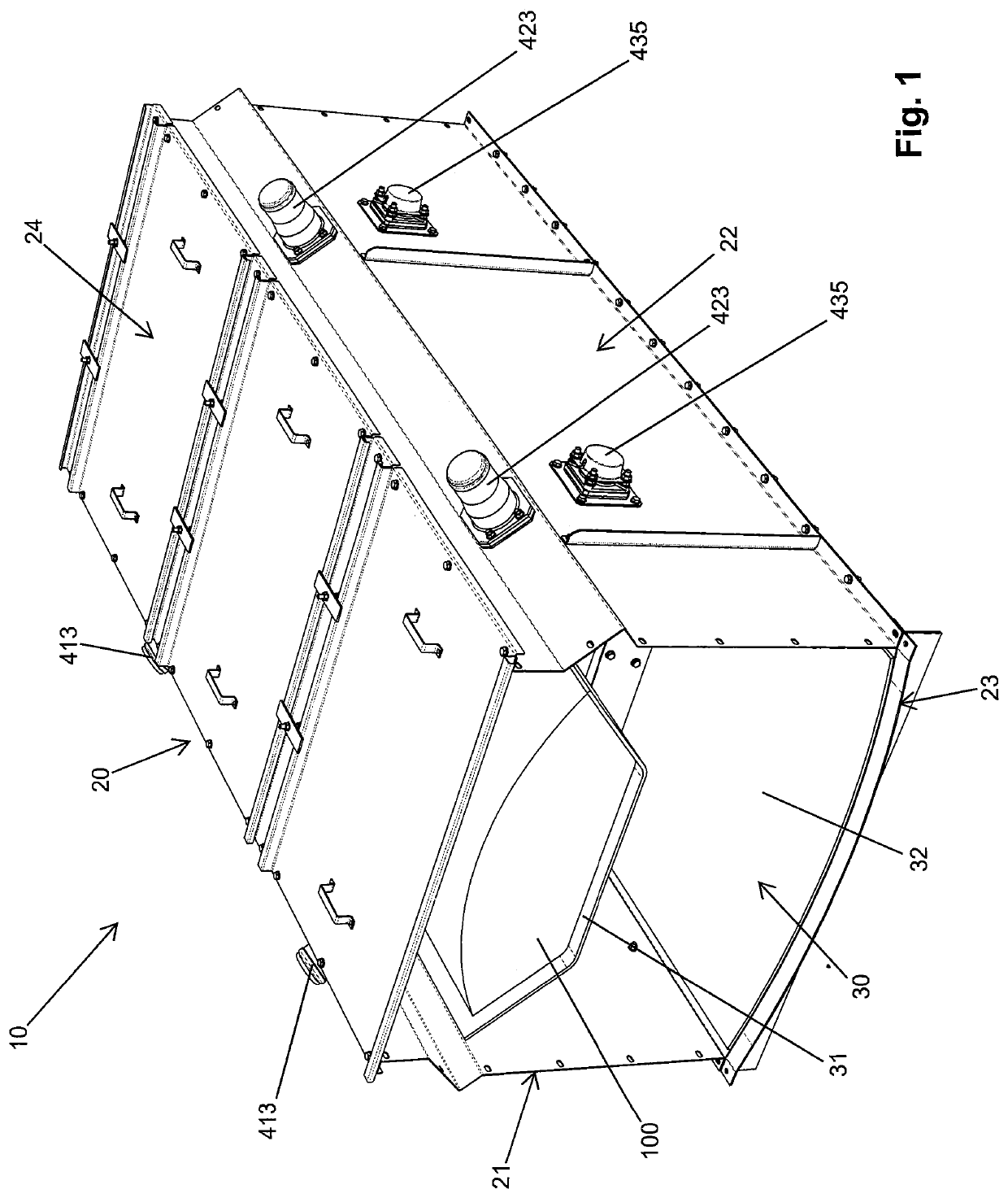
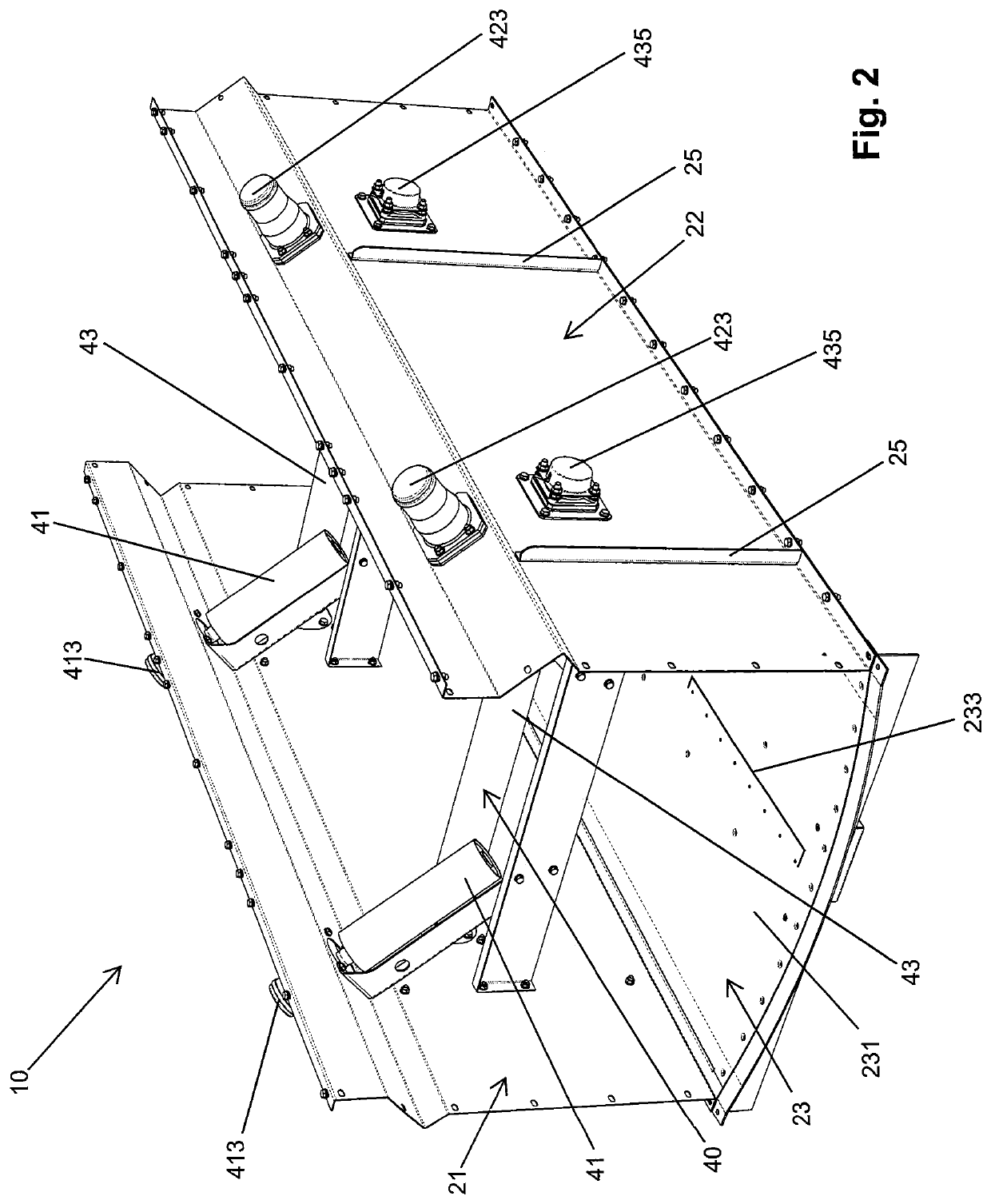
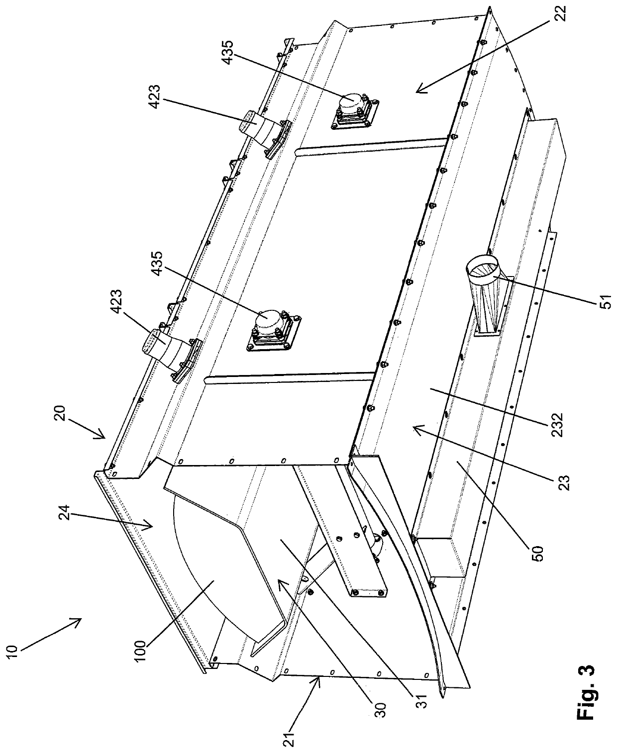
[0025]An enclosed conveyor (10) for bulk material (100) as proposed by the present invention is comprised by a plurality of interconnectable modules in its extremities by screwed unions, in order to enable a length adjustment for said enclosed conveyor (10) by the quantity of modules according to the desired application. The modules of the enclosed conveyor (10) might have different lengths, but present the same components and, therefore, the quantity of modules represented in each incorporation of the present description will be better described according to each embodiment presented.

[0026]As it can be seen in FIGS. 1, 2, 3, and 4, the enclosed conveyor (10) of the present invention comprises an enclosure (20) formed by a plurality of side walls (21,22) disposed on the bottom plate (23) and have a cover (24) disposed over said side walls (21, 22), with said bottom plate (23) having an inner surface (231) facing the interior of the enclosure (20) and an outer surface (232) facing th...


PUM


Abstract

The present invention refers to an enclosed conveyor (10) for bulk material (100), comprising an enclosure (2) having on its interior a roller (43) capable of supporting a transport portion (31) of a conveyor belt (30) and an air support system capable of supporting a return portion (32) of said conveyor belt (30). Thus, such enclosed conveyor (10) can move bulk material (100) without damaging the transport portion (31) of the conveyor belt (30), due to a higher pressure enforced by an unequal distribution of said material (100) over said transport portion (31), and also reduce the friction between the return portion (32) and a bottom plate (23) of the enclosed conveyor (10), in order to enable the proposed conveyor (10) to be manufactured at a longer length and with a smaller traction engine if compared to a conventional enclosed conveyor.

Description

TECHNICAL FIELD[0001]The present invention refers to an enclosed conveyor for bulk material comprising an enclosure having on its interior a roller capable of supporting a transport portion of a conveyor belt and an air support system capable of supporting a return portion of said conveyor belt.STATE OF THE ART[0002]Currently, conventional enclosed conveyors for bulk materials, as for example, grains, pellets, or woodchips, by a conveyor belt disposed over a set of rollers are already known. In a conventional enclosed conveyor, as the one found on the patentary document U.S. Pat. No. 6,044,965, the conveyor belt is protected against adverse climatic conditions by an enclosure, formed by a plurality of intermediate modules with different lengths, with said intermediate modules having side walls mounted on a bottom plate and a cover disposed over said side walls, by a return module, having a return roller, disposed on one extremity, and by a traction module disposed on the opposite ex...

Claims


Application Information

Patent Timeline
Patent Type & Authority Applications(United States)
IPC IPC(8): B65G15/08B65G21/08F16C29/02
CPCB65G15/08F16C29/025B65G21/08B65G15/60B65G2207/48
Inventor KUCKOSKI, ADRIANOKEISERMAN, EDISON
Owner TMSA TECH EM MOVIMENTO SA
Learn More