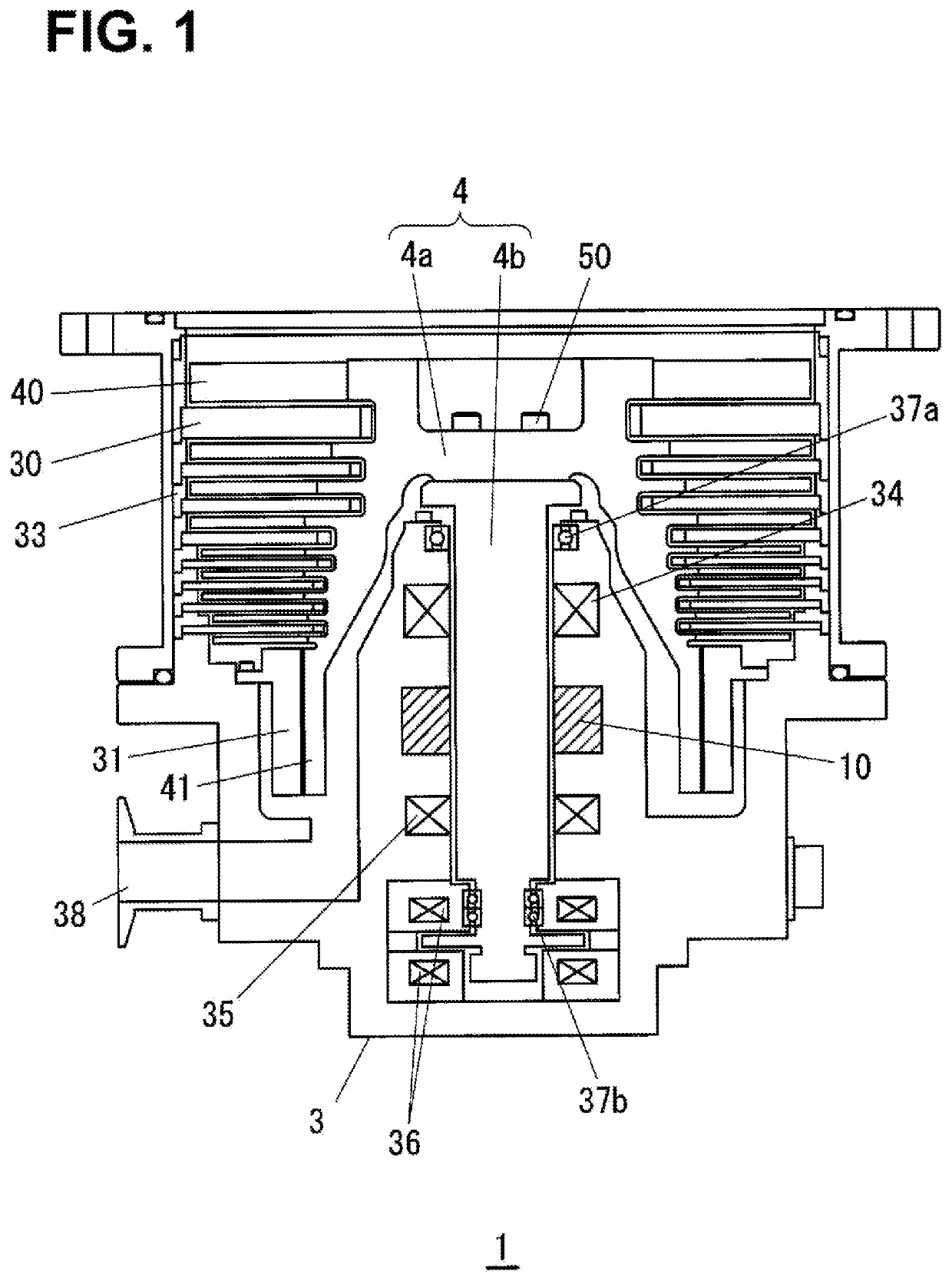
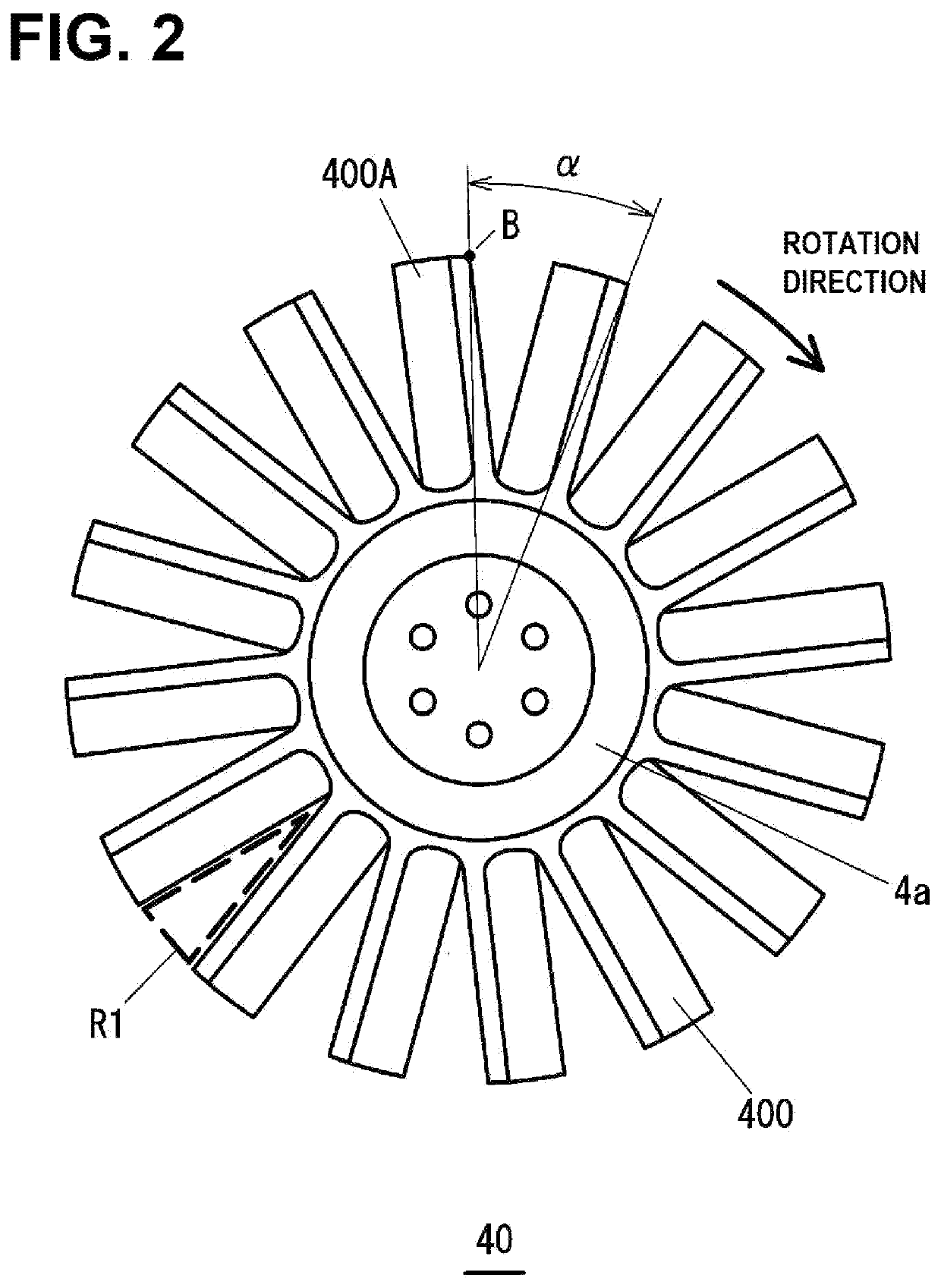
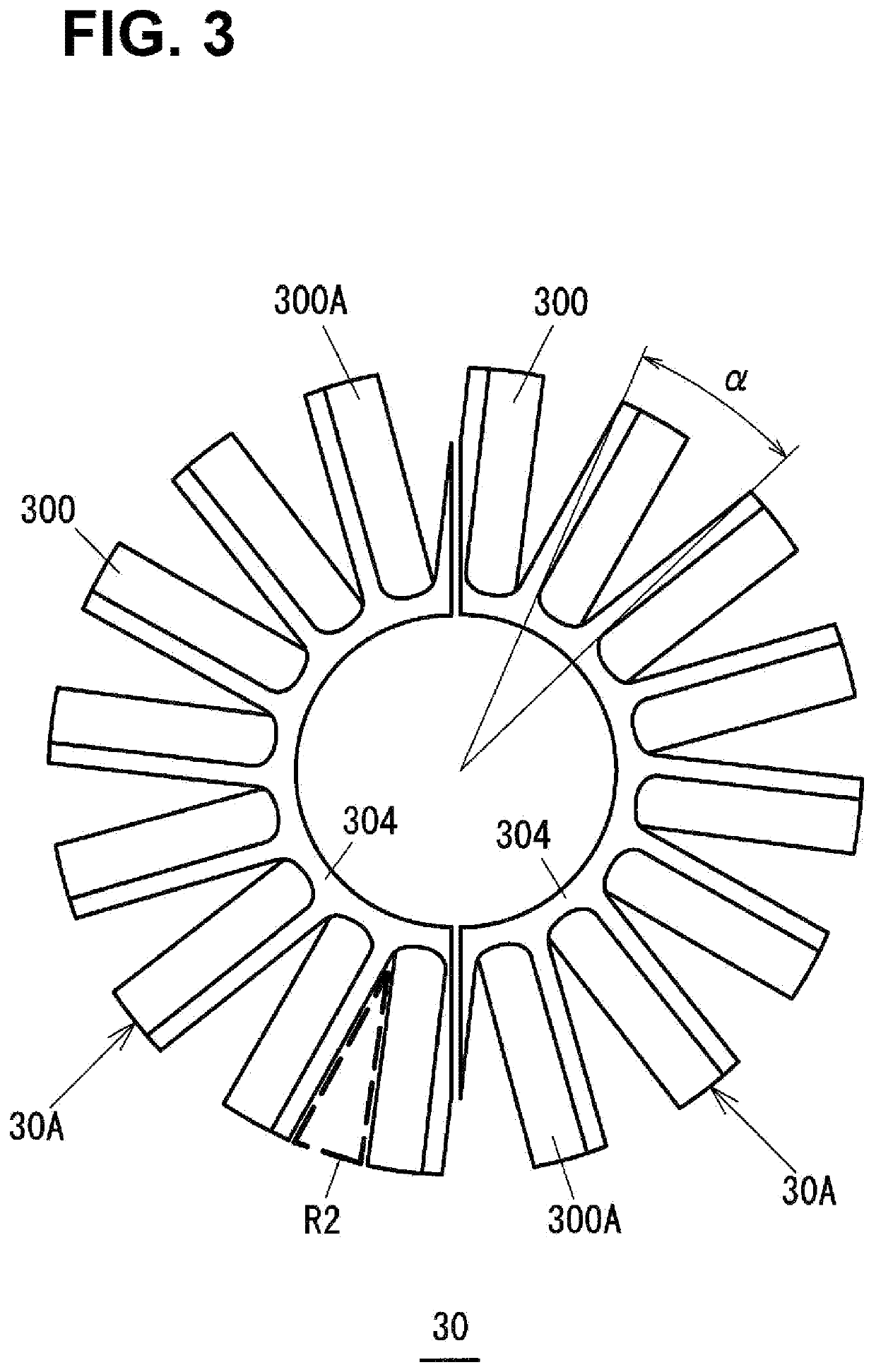
Turbo-molecular pump, rotor and stator

Active Publication Date: 2021-12-09
SHIMADZU CORP
View PDF8 Cites 0 Cited by
  • Summary
  • Abstract
  • Description
  • Claims
  • Application Information

AI Technical Summary

Benefits of technology

The invention reduces backflow and improves exhaust performance.

Problems solved by technology

However, in the turbo-molecular pump described in Patent Literature 1, the blade shape is such a complicated shape that blade inclination changes from a suction side to an exhaust side.
Thus, it is difficult to perform blade processing, and a problem that a processing cost increases is caused.

Method used


Image

  • Turbo-molecular pump, rotor and stator
  • Turbo-molecular pump, rotor and stator
  • Turbo-molecular pump, rotor and stator

Examples


example

[0070]FIGS. 9 and 10 show simulation results in a case where the rotor blade and the stator blade of the present invention were applied to an existing turbo-molecular pump. FIG. 9 shows the rate of improvement of exhaust performance (an exhaust velocity) in a case where the phase shift of the present invention was applied to a rotor blade and a stator blade of an existing 4000-L / s-class turbo-molecular pump. The first to third rows indicate a ½ pitch shift case where the phase shift is made in a cyclic manner by ½ of the inter-blade angle α, and the fourth to sixth rows indicate a ⅓ pitch shift case where the phase shift is made in a cyclic manner by ⅓ of the inter-blade angle α. For any of the ½ pitch shift and the ⅓ pitch shift, a case where only the rotor blade is phase-shifted, a case where only the stator blade is phase-shifted, and a case where both of the rotor blade and the stator blade are phase-shifted were shown. In any case, the influence of the backflow is reduced, and ...


PUM


Abstract

A turbo-molecular pump comprises multiple stages of rotor blades and multiple stages of stator blades. When m is a positive real number equal to or less than a total number of stages of the rotor blades and greater than one and K is a natural number which is not a multiple of m in a case where m is a natural number and is a natural number in a case where m is not the natural number, the multiple stages of the rotor blades include a rotor blade at an inter-blade angle α1, and a rotor blade of which reference position is phase-shifted from a reference position of the rotor blade at the inter-blade angle α1 by an angle α1·K / m.

Description

BACKGROUND OF THE INVENTION1. Technical Field[0001]The present invention relates to a turbo-molecular pump.2. Background Art[0002]A turbo-molecular pump rotates, at high speed, rotor blades formed with turbine blades relative to stator blades formed with turbine blades, thereby discharging gas molecules having flowed in through a suction port of the pump from an exhaust port of the pump. The multiple stages of the stator blades and the multiple stages of the rotor blades formed at a pump rotor are alternately arranged in a rotor axis direction. The turbine blade provides a momentum for moving to an exhaust downstream side to the gas molecule having collided with the turbine blade, and the gas molecule moves to the exhaust downstream side accordingly. Then, the gas molecule is discharged from the exhaust port of the pump.[0003]It is assumed that under high-vacuum conditions, there is almost no intermolecular collision while the gas molecule is passing through a single turbine blade s...

Claims


Application Information

Patent Timeline
IPC IPC(8): F04D19/04F04D29/18
CPCF04D19/042F04D29/181F04D19/04F04D29/002F04D29/384F04D29/388F04D29/324
Inventor FUTAGI, KEIICHI
Owner SHIMADZU CORP
Why Eureka
Try Eureka