Profiled structure for an aircraft or turbomachine
a profiled structure and turbomachine technology, applied in the direction of machines/engines, air-flow influencers, liquid fuel engines, etc., can solve the problems of large vortices at the end of the blade tips of the blower, and affecting the performance of the turbojet engin
- Summary
- Abstract
- Description
- Claims
- Application Information
AI Technical Summary
Benefits of technology
Problems solved by technology
Method used
Image
Examples
Embodiment Construction
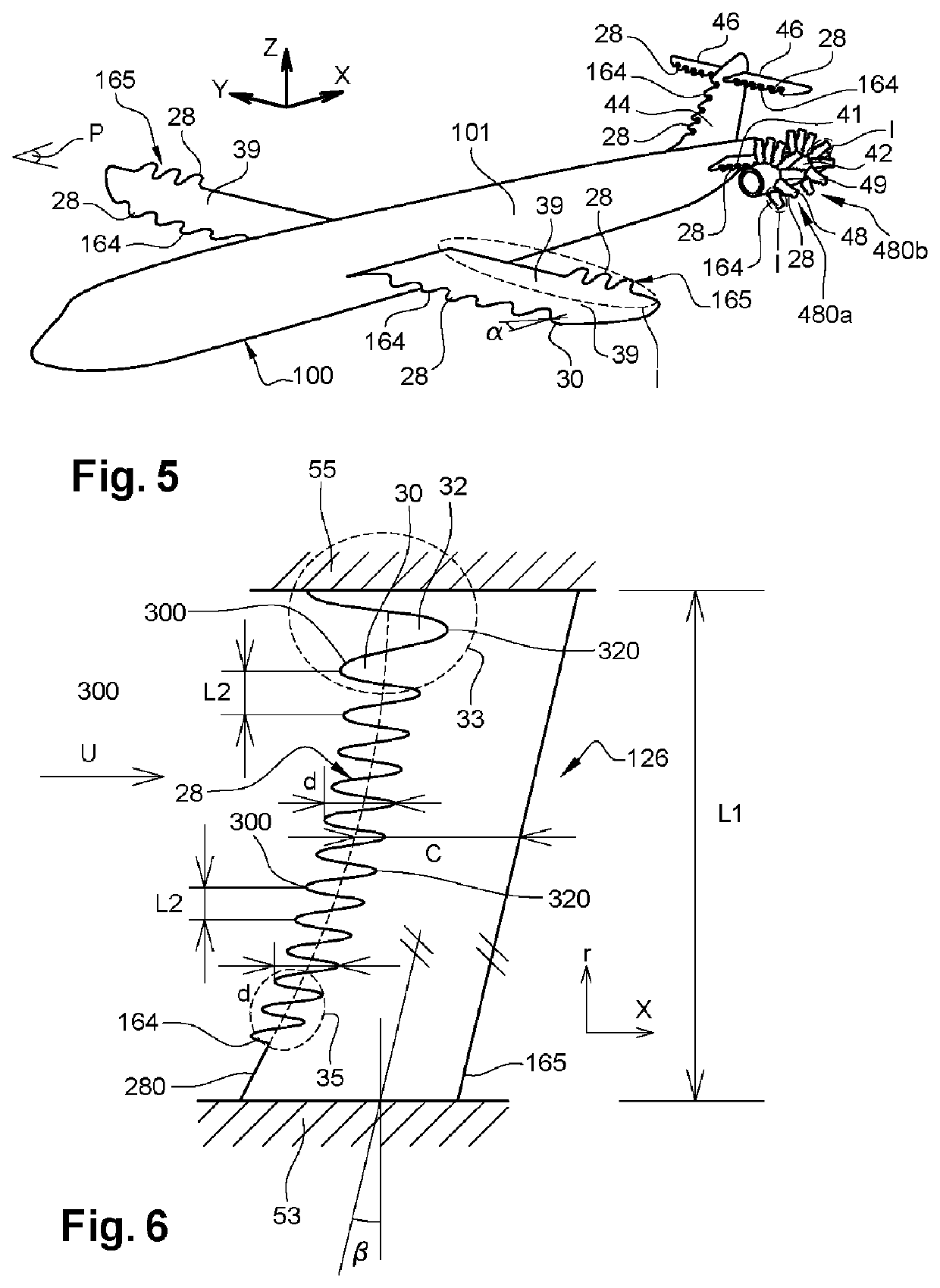
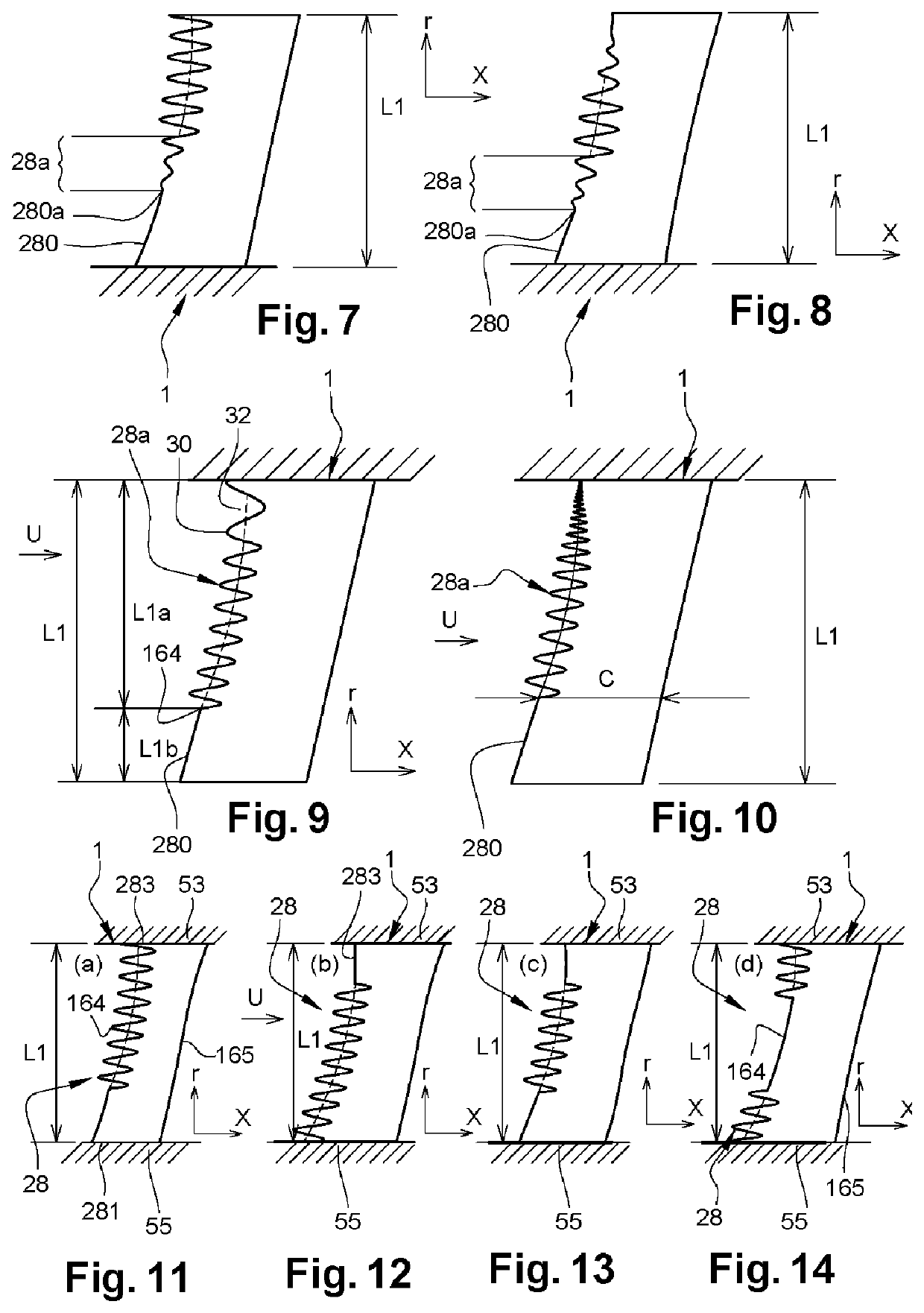
[0064]Even if this is not very clear to the eye, it must be considered that in all FIGS. 2-17 and 23-25 the variations in amplitude (d) and / or spacing (L2) between two successive vertices of teeth or of depressions are monotonic under the above conditions.
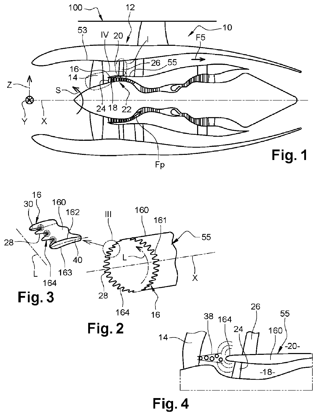
[0065]Referring to FIG. 1, an aircraft 100 turbojet 10 is schematically represented and defined as follows:
[0066]The pod 12 is used as the outer casing for the various components, including, at the front (left in FIG. 1), an upstream fan 14 (US).
[0067]Downstream (DS) of the fan 14, the airflow (locally shown in 38 in FIG. 4) is separated by the separator beak 16 of an annular wall 160 into a primary airflow and a secondary airflow. The primary airflow flows through an inner annular air passage or primary vein 18 when entering the low-pressure compressor 22 at the intake guide blades 24 IGV. The secondary airflow is diverted by the separator beak 16 into an external annular air passage 20 (secondary vein) towards the outlet guide bl...
PUM
 Abstract
Description
Claims
Application Information
 - R&D
- Intellectual Property
- Life Sciences
- Materials
- Tech Scout
- Unparalleled Data Quality
- Higher Quality Content
- 60% Fewer Hallucinations
Browse by: Latest US Patents, China's latest patents, Technical Efficacy Thesaurus, Application Domain, Technology Topic, Popular Technical Reports.
© 2025 PatSnap. All rights reserved.Legal|Privacy policy|Modern Slavery Act Transparency Statement|Sitemap|About US| Contact US: help@patsnap.com


