Supercharge Your Innovation With Domain-Expert AI Agents!

Fault detecting system for coaxial transmission lines

a fault detection and coaxial transmission technology, applied in the field of coaxial transmission line fault detection system, to achieve the effect of accurate position of factor and/or spark/ar

Pending Publication Date: 2021-12-16
DAC SYST SA
View PDF3 Cites 0 Cited by
  • Summary
  • Abstract
  • Description
  • Claims
  • Application Information

AI Technical Summary

Benefits of technology

The invention aims to provide a device that can accurately detect the position of a factor or spark / arc in a coaxial cable or line.

Problems solved by technology

In wireless transmission systems based on coaxial transmission lines, two physical phenomena can cause malfunction of the system or even safety risks for the operators: sparks (dielectric discharge) in the coaxial cable / line and degradation (up to failure) of the coaxial cable / line.
Nevertheless, several factors may affect the performance of the system, reducing the breakdown threshold and / or increasing the peak voltage applied to the inner conductor because of the introduction of reflections that can cause stationary waves in the line.
As illustrated in FIG. 2, examples of these factors are:Deformation of the conductors due to excessive mechanical stress with consequent loss of cylindrical symmetry;Deformation of the conductors and / or the plastic (usually Teflon®) parts in the line due to aging and thermal cycles;Defects in the construction of the mechanical parts;Accidental damages during maintenance operations;Damages caused by animals (mice, birds) in the station;Human mistakes in the mounting during the installation;Presence of humidity, dust, unwanted material inside the line.
The effect may cause permanent damages to the metal wails of the line, causing in the long term a loss of performance and even a physical destruction, with potentially dangerous consequences in high power systems (total system failure, fires, explosion).
Accidental damages in invisible positions (rodents, for example) can cause total failure that can be hard to localize in a long transmission line running in a complex infrastructure.
Small deformations, little quantities of unwanted materials, small imperfection in the installation may be invisible in the short term and have too small effects to enable a spark.
Nevertheless, it is still possible a local degradation of the performance that, for example, causes a localized effect that from the electrical point of view may be regarded as a parasitic resistance in series with the line.
The resistance will therefore dissipate an unwanted amount of power in the form of heat.
In time, this spurious heat dissipation can cause a localized overheating and in the worst cases reach the melting point for the plastic parts, causing a sudden and potentially destructive failure.
However, these solutions may be effective to detect a presence of a spark in the line, but none of them is able to localize the exact position of the spark within a line.
These techniques allow to detect discontinuities in the cables with low spatial resolution and amplitude accuracy.
However, currently available TDR instruments cannot provide a fault localization while the cable is operating, i.e. providing a service signal (TV or Radio in our case).

Method used


Image

  • Fault detecting system for coaxial transmission lines
  • Fault detecting system for coaxial transmission lines
  • Fault detecting system for coaxial transmission lines

Examples


Embodiment Construction

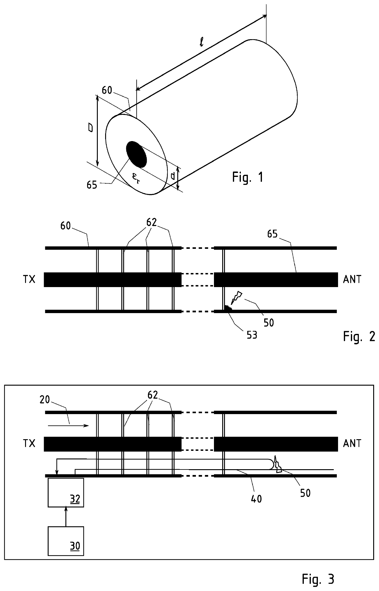
[0048]FIGS. 1 and 2 show a typical rigid coaxial transmission line, as those used in radio and television broadcast towers for VHF and UHF signals. The invention is particularly suited for monitoring such installations but is not limited thereto and could be used to determine faults in any possible transmission line. Since the detection system of the invention relies on ultra-wide bandwidth emissions, it can be used successfully in a large variety of transmission lines.

[0049]The proposed detection system (device) consists of a guided radar, that is a radar signal propagating inside the transmission line. The system generates a train of radar pulses at a carrier frequency outside the range of the service signal, in order to avoid introducing any disturbance.

[0050]The system comprises a transmitter configured to emit a radar signal in a predetermined direction inside the transmission line (waveguide, such as a coaxial cable or a coaxial line) and a radar receiver configured to capture...


PUM


Abstract

A device for testing faults and non-conformities in a waveguide, such as a coaxial cable or a coaxial line such as those used in radio and television broadcast towers or in cellphone towers. The device is arranged for injecting a signal in the waveguide and for receiving a backscattered signal, characterizing a nonconformity or a fault. The injected signal may be a digital UWB signal.

Description

REFERENCE DATA[0001]The present application is a national phase of international patent application PCT / IB2019 / 058846 of Oct. 17, 2019 claiming priority of Swiss patent application CH 01284 / 18 of Oct. 22, 2018.FIELD OF THE INVENTION[0002]The present invention concerns a system able to detect and localize sparks and degradations in coaxial transmission lines.RELATED ART[0003]The present system applies, among others, to transmitting or transmitting / receiving system based on a signal generator (transmitter, with or without a receiver) connected to an antenna by means of a coaxial transmission line. The invention can be usefully applied to the monitoring and diagnostics of broadcasting stations and transmitters in mobile data networks, including:[0004]Transmitting stations for FM analogic Radio Broadcast;[0005]Transmitting stations for Digital Radio Broadcast (DAB);[0006]Transmitting stations for Digital TV Broadcast in any standard (DVBT, ATSC and all future evolutions);[0007]Mobile te...

Claims


Application Information

Patent Timeline
Patent Type & Authority Applications(United States)
IPC IPC(8): G01R31/11H04B3/46H04L27/18
CPCG01R31/11H04L27/18H04B3/46
Inventor DELMASTRO, PAOLOMAGGIORA, RICCARDOSALVADOR, SARA MARINA
Owner DAC SYST SA
Features
  • R&D
  • Intellectual Property
  • Life Sciences
  • Materials
  • Tech Scout
  • Unparalleled Data Quality
  • Higher Quality Content
  • 60% Fewer Hallucinations
Learn More