Eureka AIR delivers breakthrough ideas for toughest innovation challenges, trusted by R&D personnel around the world.

Self-assembly apparatus and method for semiconductor light emitting device

a self-assembling and light-emitting technology, applied in the field of display devices, can solve the problems of short life span, low efficiency of backlighting light, and not so fast response time, and achieve the effects of minimizing frictional force, improving transfer accuracy, and low cos

Pending Publication Date: 2021-12-23
LG ELECTRONICS INC
View PDF0 Cites 0 Cited by
  • Summary
  • Abstract
  • Description
  • Claims
  • Application Information

AI Technical Summary

Benefits of technology

This patent describes a new manufacturing process for large-screen displays using micro-sized semiconductor light emitting devices. The process has high reliability and can improve transfer precision for self-ass näbed semiconductor light emitting devices. The method allows for the large number of devices to be transferred onto a low-cost large-area substrate. The process also minimizes friction between the substrate and semiconductor light emitting device during transfer, preventing damage and improving transfer accuracy. Additionally, the process allows for accurate placement of the semiconductor light emitting devices on the substrate using a magnetic force, even if the substrate is bent during transfer. Overall, this patent describes a cost-effective method for manufacturing large-size displays using micro-sized semiconductor light emitting devices.

Problems solved by technology

However, there exist problems such as not-so-fast response time, low efficiency of light generated by backlight in case of LCDs, and there exist drawbacks such as short life span, not-so-good yield as well as low efficiency in case of OLEDs.
However, since a large-sized display requires millions of semiconductor light emitting devices, it has difficulty in transferring the devices compared to other technologies.
In recent years, U.S. Pat. No. 9,825,202 proposed a micro-LED structure suitable for self-assembly, but there is not yet research on technologies for manufacturing a display through self-assembly of micro-LEDs.

Method used


Image

  • Self-assembly apparatus and method for semiconductor light emitting device
  • Self-assembly apparatus and method for semiconductor light emitting device
  • Self-assembly apparatus and method for semiconductor light emitting device

Examples


Embodiment Construction

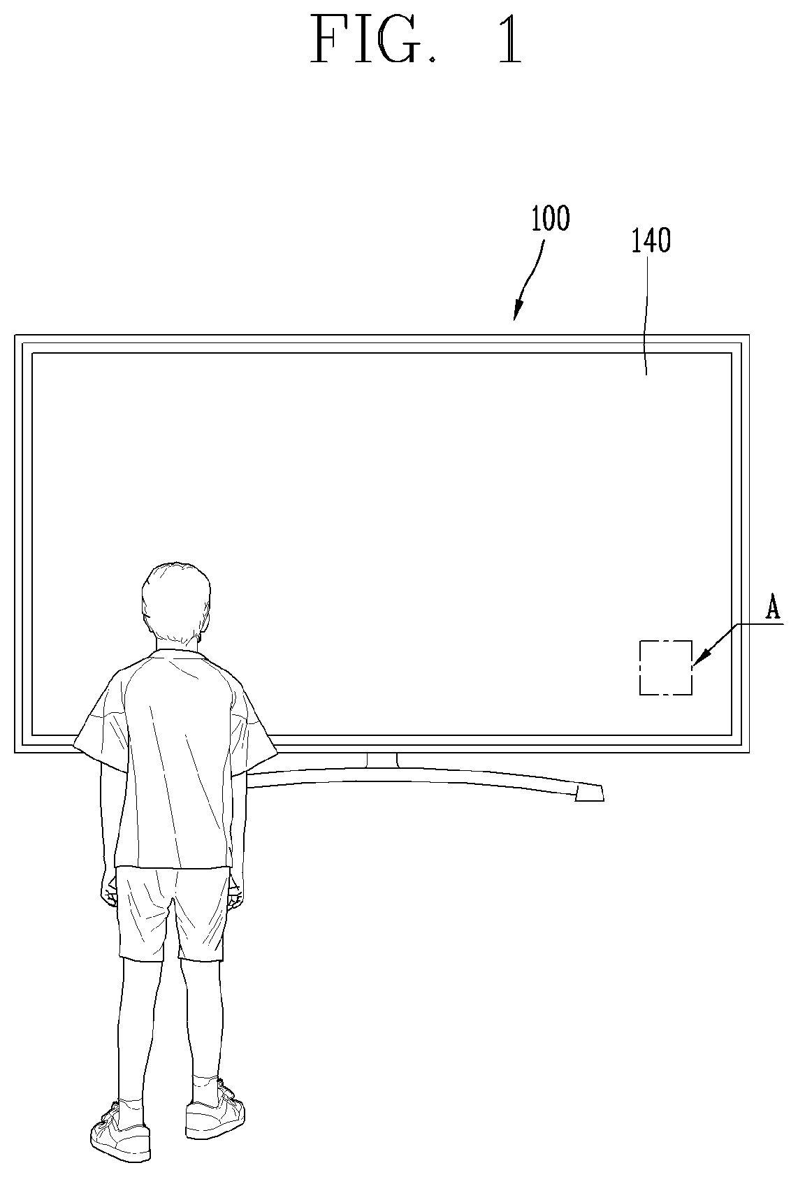
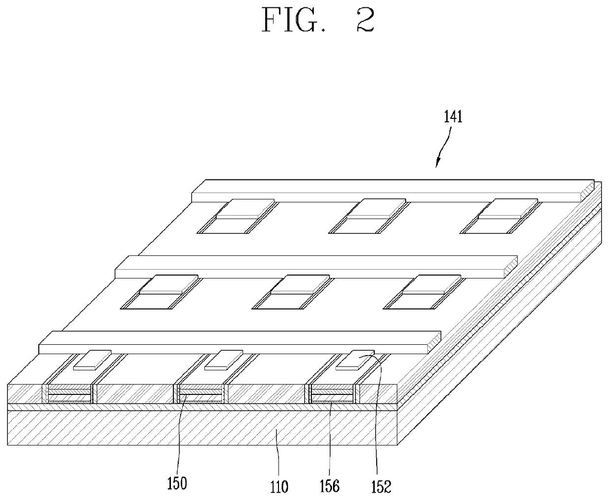
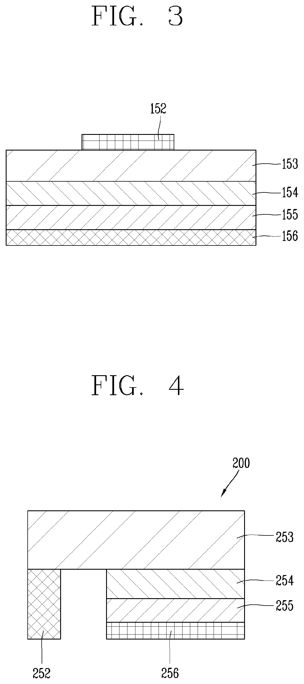
[0045]Hereinafter, the embodiments disclosed herein will be described in detail with reference to the accompanying drawings, and the same or similar elements are designated with the same numeral references regardless of the numerals in the drawings and their redundant description will be omitted. A suffix “module” and “unit” used for constituent elements disclosed in the following description is merely intended for easy description of the specification, and the suffix itself does not give any special meaning or function. In describing an embodiment disclosed herein, moreover, the detailed description will be omitted when specific description for publicly known technologies to which the invention pertains is judged to obscure the gist of the present disclosure. Also, it should be noted that the accompanying drawings are merely illustrated to easily explain the concept of the invention, and therefore, they should not be construed to limit the technological concept disclosed herein by ...


PUM

PropertyMeasurementUnit
diameteraaaaaaaaaa
sizeaaaaaaaaaa
magnetic forceaaaaaaaaaa

Abstract

Discussed is a self-assembly apparatus of a semiconductor light emitting device, the self-assembly apparatus including a fluid chamber configured to accommodate a plurality of semiconductor light emitting devices, each semiconductor light emitting device having a magnetic body; a magnet disposed to be spaced apart from the fluid chamber and configured to apply a magnetic force to the plurality of semiconductor light emitting devices; and a position controller connected to the magnet, and configured to control a position of the magnet; and a power supply configured to induce formation of an electric field on a substrate placed at an assembly position so that the plurality of semiconductor light emitting devices are seated at preset positions on the substrate while being moved due to a positional change of the magnet, wherein the position controller transfers the magnet in one direction while rotating the magnet about a rotation axis for the magnet.

Description

BACKGROUND1. Technical Field[0001]The present disclosure relates to a method of manufacturing a display device, and more particularly, to a method and apparatus of self-assembling a semiconductor light emitting device.2. Description of the Related Art[0002]In recent years, liquid crystal displays (LCDs), organic light emitting diode (OLED) displays, and micro-LED displays have been competed to implement a large-area display in the field of display technology.[0003]However, there exist problems such as not-so-fast response time, low efficiency of light generated by backlight in case of LCDs, and there exist drawbacks such as short life span, not-so-good yield as well as low efficiency in case of OLEDs.[0004]On the contrary, when semiconductor light emitting devices (micro-LED (μLED)) having a diameter or a cross sectional area of 100 microns or less are used in a display, the display may provide a very high efficiency because it does not absorb light using a polarizing plate or the l...

Claims


Application Information

Patent Timeline
Patent Type & Authority Applications(United States)
IPC IPC(8): H01L33/00H01L25/075
CPCH01L33/005H01L21/68H01L25/0753H01L2224/95101H01L24/95H01L21/67144H01L2924/12041H01L2224/95085H01L2224/95133H01L21/67259H01L21/67709H01L21/67721H01L33/0093
Inventor CHO, HYUNWOOSHIM, BONGCHU
Owner LG ELECTRONICS INC
Why Eureka
Eureka Blog
Learn More