Atmosphere purification reactor using electron beam and atmosphere purification apparatus including the same

a technology of atmosphere purification and electron beam, which is applied in the direction of chemistry apparatus and processes, separation processes, and dispersed particle separation, etc., can solve the problems of reducing reducing the efficiency of the reactor, and increasing the size of the limit, so as to reduce the internal pressure of the reactor and prevent the effect of process efficiency and process efficiency improvemen

Pending Publication Date: 2021-12-30
KOREA ATOMIC ENERGY RES INST
View PDF0 Cites 0 Cited by
  • Summary
  • Abstract
  • Description
  • Claims
  • Application Information

AI Technical Summary

Benefits of technology

[0012]According to the present invention, since flue gas passes through an inside of a reactor while rotating, even when a low energy electron beam is used, the electron beam can be entirely and uniformly emitted to the flue gas. Accordingly, since generation of a dead zone is prevented in the reactor, even when the low energy electron beam is used, a required process capacity can be sufficiently secured.
[0013]In addition, according to the present invention, since electron beams emitted by two electron beam generators overlap in the reactor due to two transmissive parts collinear with each other, even when a diameter of a housing is increased, a decrease in process efficiency can be prevented.
[0014]In addition, according to the present invention, since two reactors are connected in series and portions thereof connected to each other form a Venturi tube, process efficiency can be improved and an internal pressure of the reactor can also be reduced through sequential purification. Accordingly, even though the present invention uses the low energy electron beam, the process efficiency can be improved, and durability of the reactors can be improved.
[0015]In addition, according to the present invention, since overall equipment can be miniaturized according to the present invention, self-shielding is possible, and a cost can be significantly reduced when compared to a conventional case in which a high energy electron beam method is used.

Problems solved by technology

Generally, since an effective transmission depth of an electron beam is two thirds of a maximum transmission depth thereof, the electron beam emitted through the emitting window is lossed a considerable amount of energy (more than 30%).
Accordingly, since the conventional atmosphere purification reactor for processing the large amount of flue gas should use the electron accelerator having beam energy which is higher than necessary, there is a limit in that a size has to be increased.
Accordingly, since a size of a chamber for shielding against radiation should be considerably increased, there is a problem in that an installation cost is also considerably increased.

Method used


Image

  • Atmosphere purification reactor using electron beam and atmosphere purification apparatus including the same
  • Atmosphere purification reactor using electron beam and atmosphere purification apparatus including the same
  • Atmosphere purification reactor using electron beam and atmosphere purification apparatus including the same

Examples


Embodiment Construction

[0033]Hereinafter, embodiments of the present invention will be described in detail with reference to the accompanying drawings in order for those skilled in the art to easily perform the present invention. The present invention may be implemented in several different forms and is not limited to the embodiments described herein. Parts irrelevant to description are omitted in the drawings in order to clearly explain embodiments of the present invention. Similar or the same parts are denoted by similar reference numerals throughout this specification.

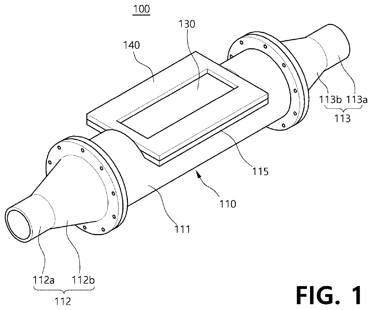
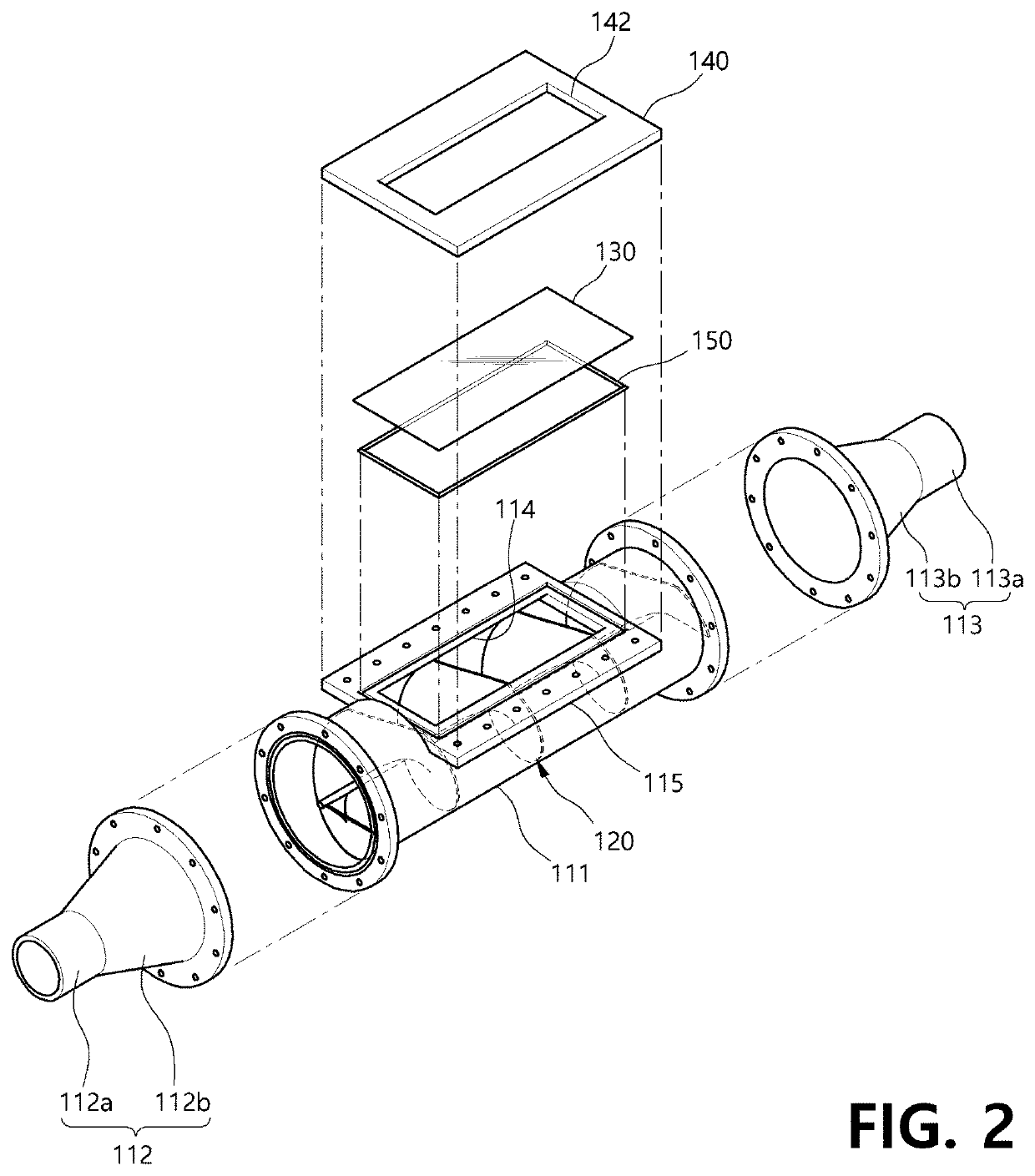
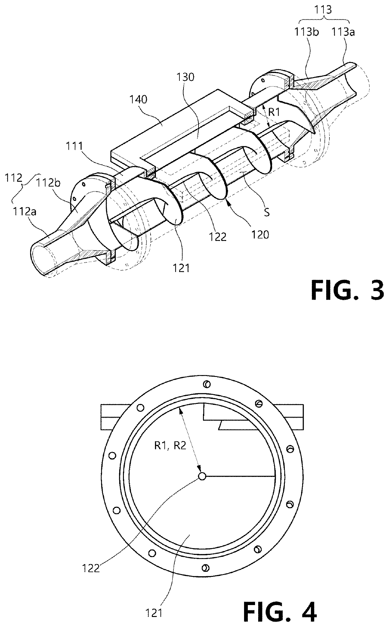
[0034]In an atmosphere purification reactor using an electron beam (hereinafter, referred to as an ‘atmosphere purification reactor’) 100, 200, or 300 according to one embodiment of the present invention, since a fluid, such as flue gas, introduced from the outside moves while rotating, even when a low energy electron beam is used, the low energy electron beam may be uniformly emitted to the flue gas.

[0035]To this end, as illustrated in F...


PUM


Abstract

An atmosphere purification reactor using an electron beam and an atmosphere purification apparatus including the same are disclosed. The atmosphere purification reactor using an electron beam according to an exemplary embodiment of the present invention includes a housing which has a predetermined length and is formed to have a hollow form such that a fluid introduced from an outside passes through the housing, a guide part which is disposed in the housing in a longitudinal direction and guides a moving path of the fluid such that the fluid moves while rotating, and a transmissive part which is provided at one side of the housing so as to transmit an electron beam into the housing.

Description

TECHNICAL FIELD[0001]The present invention relates to an atmosphere purification reactor using an electron beam and an atmosphere purification apparatus including the same.BACKGROUND ART[0002]Various atmosphere purification technologies using electron accelerators have been introduced worldwide since the 1990s, and various atmosphere purification technologies using electron beams have been domestically introduced in South Korea since the 2000s.[0003]However, emitting windows, which transmit electron beams, of general electron accelerators applied to atmosphere purification technologies have rectangular shapes, and only lateral lengths of the emitting windows are changed according to users' environments and beam energy.[0004]A transmission depth of an electron beam emitted from an electron accelerator is determined by an acceleration voltage of the electron accelerator, that is, beam energy. Generally, since an effective transmission depth of an electron beam is two thirds of a maxim...

Claims


Application Information

Patent Timeline
Patent Type & Authority Applications(United States)
IPC IPC(8): B01D53/00B01D53/24
CPCB01D53/007B01D2259/812B01D2258/0283B01D53/24B01D53/323B01D2258/0291
Inventor KIM, BYUNG NAMLEE, MYUNJOOLIM, YOURI MOOKJANG, KYU HACHUNG, BYUN YOUNG
Owner KOREA ATOMIC ENERGY RES INST
Why Eureka
Try Eureka