Apparatus and methods for producing tubular packages

a technology of apparatus and tubular packaging, applied in the directions of packaging, transportation and packaging, successive articles, etc., can solve the problems of greater dead-fold properties of semi-rigid materials, and achieve the effects of reducing friction, facilitating manufacturing and setting up, and facilitating cleaning

Pending Publication Date: 2021-12-30
INTERCONTINENTAL GREAT BRANDS LLC
View PDF2 Cites 2 Cited by
  • Summary
  • Abstract
  • Description
  • Claims
  • Application Information

AI Technical Summary

Benefits of technology

[0019]In apparatus in accordance with the invention, the packaging material is folded from a planar configuration incrementally by the package formers in the series. The use of a series of formers is advantageous as it is easier to manufacture and set up, is easier to clean, and leads to a reduction in friction compared to a former having a continuous broad surface over which the packaging material is drawn. For use with semi-rigid packaging materials, such as paperboard or cartonboard, it is expected the folding operation will be carried out over a greater distance than is the case with conventional HFFS or VFFS apparatus. Accordingly, in apparatus in accordance with the invention, the forming section may extend over a length as measured in the machine direction of 1 m or more, or 1.5 m or more, or 2 m or more or 3 m or more. Alternatively, the forming section may extend over a length as measured in the machine direction which is at lea

Problems solved by technology

Whilst this achievable with the highly flexible polymeric films typically used in flow-wrap packaging, it presents difficulties with semi-rigid materials having greate

Method used


Image

  • Apparatus and methods for producing tubular packages
  • Apparatus and methods for producing tubular packages
  • Apparatus and methods for producing tubular packages

Examples


first embodiment

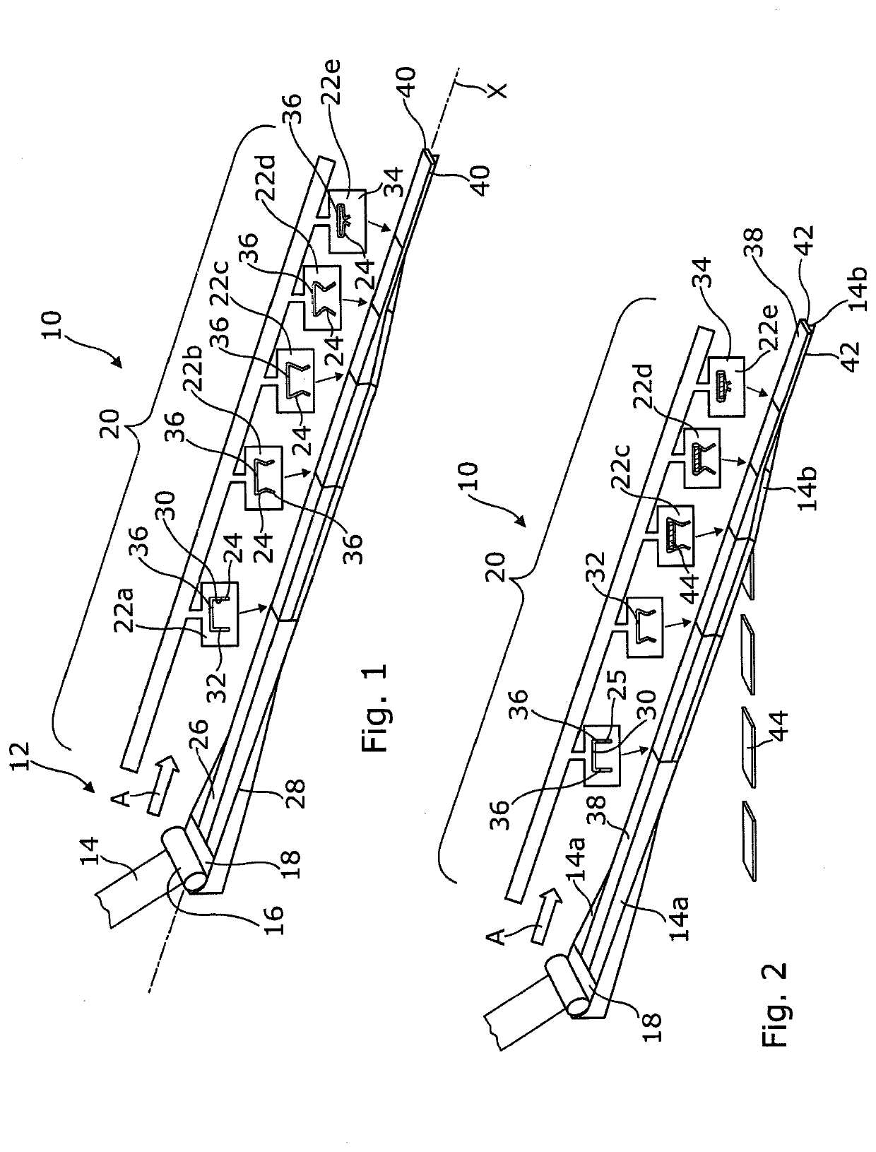
[0060]FIG. 2 is a further schematic illustration of the apparatus of FIG. 1 exemplifying an arrangement for introducing items into the packaging.

second embodiment

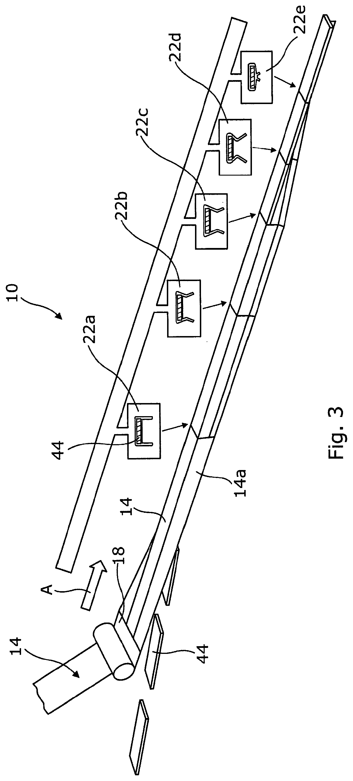
[0061]FIG. 3 is a still further schematic illustration of the apparatus of FIG. 1 exemplifying an arrangement for introducing items into the packaging.

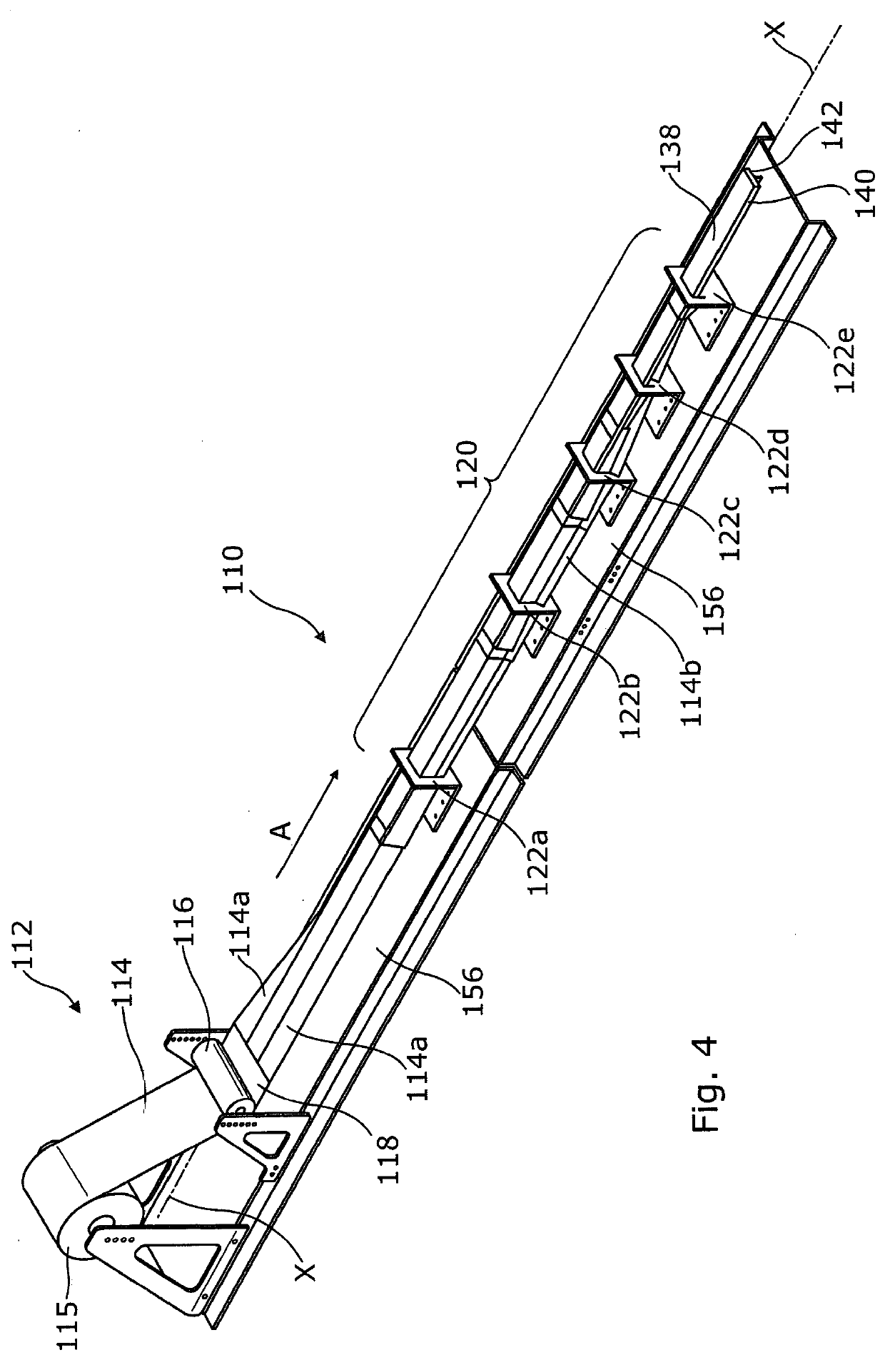
[0062]FIG. 4 is a perspective, partly schematic illustration showing a second embodiment of apparatus for manufacturing packaging in accordance with an aspect of the present invention.

[0063]FIG. 5 is a perspective view of a first package former forming part of the apparatus of FIG. 4.

[0064]FIG. 6 is an end view of the first package former of FIG. 5 taken in the direction of arrow B in FIG. 5.

[0065]FIG. 7 is a perspective view of a second package former forming part of the apparatus of FIG. 4.

[0066]FIG. 8 is an end view of the second package former of FIG. 7 taken in the direction of arrow C in FIG. 7.

[0067]FIG. 9 is a perspective view of a third package former forming part of the apparatus of FIG. 4.

[0068]FIG. 10 is an end view of the third package former of FIG. 9 taken in the direction of arrow D in FIG. 9.

[0069]FIG. 11 is a perspec...


PUM

PropertyMeasurementUnit
Angleaaaaaaaaaa
Angleaaaaaaaaaa
Angleaaaaaaaaaa

Abstract

Apparatus (10) for producing tubular packages includes a packaging material dispenser (12) and a forming section (20). The forming section (20) comprises a series of package formers (22a-22e) aligned in the machine direction, each defining a packaging material folding channel (24) through which the packaging material passes. The channels (24) of the package formers in the series vary in shape such that as the packaging material passes through the forming section it is gradually folded about a longitudinal axis from a planar configuration into a tubular structure. A series of items (44) to be packaged is conveyed in the machine direction and may be sequentially introduced proximal to the packaging material (14) at a location such that the packaging material is subsequently folded about each item in turn as it continues through the forming section. The apparatus may be a horizontal or vertical form, fill seal type apparatus. The packaging material (14) may be a semi-rigid packaging material such as paperboard, cartonboard, or semi-rigid plastics.

Description

TECHNICAL FIELD OF THE INVENTION[0001]The present invention relates to apparatus and methods for packaging. The apparatus and methods are especially, but not exclusively, suitable for packaging items in tubular packaging made from a semi-rigid packaging material, such as paperboard, cartonboard, and semi-rigid plastic, in a substantially continuous process.BACKGROUND TO THE INVENTION[0002]It is known to provide so-called flow-wrap packaging which consists of a flexible tubular container sealed at either end, normally with crimping or embossing to provide patterned sealing portions.[0003]In general, this type of flow-wrap packaging is manufactured by horizontal or vertical form, fill and seal processes (HFFS or VFFS). In HFFS processes, a flexible packaging film is run through machinery which folds the material around an item and then clamps and seals the ends of the folded material followed by cutting, to provide a sealed packaging. Such packaging can be run through appropriate mach...

Claims


Application Information

Patent Timeline
IPC IPC(8): B65B9/087
CPCB65B9/087B65B2009/063B65B2220/08B65B9/06
Inventor FERRIS, KEVINBORTOS, DANIELMUMAN, LEESHA
Owner INTERCONTINENTAL GREAT BRANDS LLC
Why Eureka
Try Eureka