
Crimping assembly, tool and die design

a technology of crimping tool and die set, which is applied in the direction of line/current collector details, electrical equipment, connections, etc., can solve the problems of existing crimping tools, unable to crimp 1000 kcmil lugs with ton crimping tools, and loss of connection

Pending Publication Date: 2021-12-30
ILSCO
View PDF0 Cites 1 Cited by
  • Summary
  • Abstract
  • Description
  • Claims
  • Application Information

AI Technical Summary

Benefits of technology

The invention is a die set that can be used in a crimping tool for fitting a 1000 kcmil lug. This avoids the need for a separate crimping tool and allows for easier conversion between circular mils and wire diameter. The invention has increased versatility and strength compared to current U-dies, making it more appealing to contractors. Additionally, it allows for crimping of a wider range of sizes and is preferred by many users as a single-point indentor tool.

Problems solved by technology

For example, when installing electrical connectors to conductor ground wires, it is particularly imperative that the materials stay connected even under stress or otherwise the connection is lost.
However, some existing crimping tools such as 12-ton crimping tools cannot crimp a 1000 kcmil lug due to physical constraints which do not allow the 1000 kcmil lugs to fit between the jaws of a 12-ton tool when the dies are in place.
This option requires a high inventory of dies and tools which is expensive and inefficient in the field.
The inventory of crimping tools and necessary dies makes such a solution impractical.

Method used


Image

  • Crimping assembly, tool and die design
  • Crimping assembly, tool and die design
  • Crimping assembly, tool and die design

Examples


second embodiment

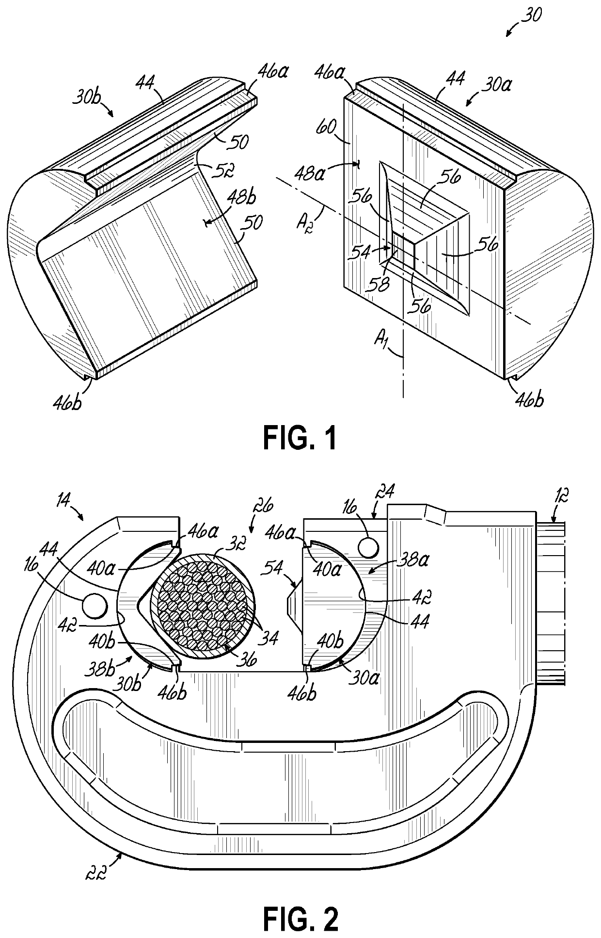
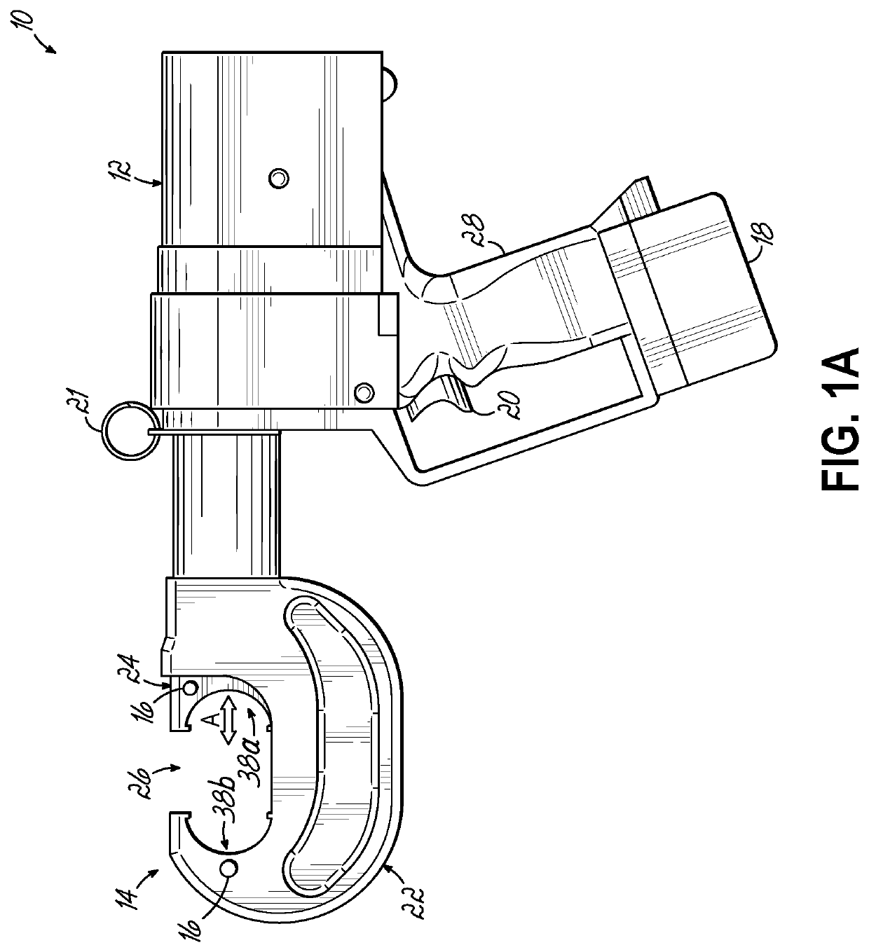
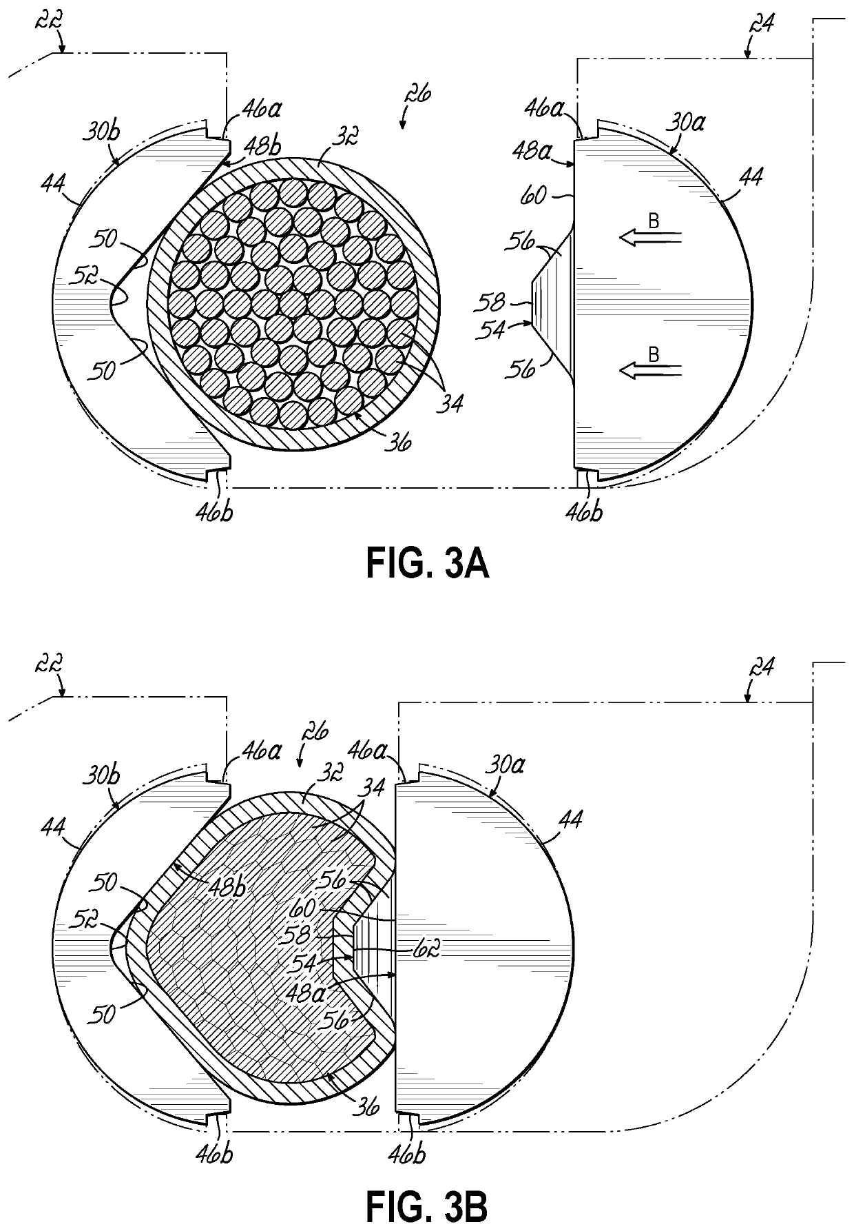
[0058]a die set 30 according to this invention is show in FIG. 4 with the die set 30 mated with the crimping tool 10 shown in FIG. 5. Elements of the die set 30, crimping tool 10, lug 32 and conductor 36 similar to those of the earlier embodiment are identified by similar reference numerals. The lower die 30b of the die set 30 of FIG. 4 is similar to or the same as the lower die 30b of the die set 30 of FIG. 1. The upper die 30a of FIG. 4 differs from the upper die of FIG. 1 by the addition of added indenting members in the form of a pair of rims 54a, 54b each projecting forwardly from the base 60 at a juncture between the base 60 and the associated groove 46 of the upper die 30a. The rims 54a, 54b form recesses 64a, 64b in the lug 32 and adjacent wires 34 of the conductor 36 as shown in FIGS. 6B an 6C. The height of each rim 54a, 54b is less than that of the pyramidal shaped indenting member 54 in the embodiment of FIGS. 4-6C, although other configurations and shapes are within the...

third embodiment

[0059]a die set 30 according to this invention is show in FIG. 7 with the die set 30 mated with the crimping tool 10 shown in FIG. 8. Elements of the die set 30, crimping tool 10, lug 32 and conductor 36 similar to those of the earlier embodiments are identified by similar reference numerals. The lower die 30b of the die set 30 of FIG. 4 is similar to or the same as the lower die 30b of the die set 30 of FIGS. 1 and 4. The upper die 30a of FIG. 7 differs from the upper dies 30a of FIGS. 1 and 4 by the shape of the indenting member 54 on the working surface 48a. The indenting member 54 of the upper die 30a of the die set 30 of FIG. 7 is a saddle shaped member with a pair of generally oval shaped pockets 66 spaced on either side of a laterally oriented ridge 68. Each of the oval shaped pockets 66 is adjacent to one of the grooves 46 of the upper die 30a. The indenting member 54 of the upper die 30a of FIG. 7 forms a central indentation 62 in the lug 32 bordered on the upper and lower ...

fifth embodiment

[0060]A fourth and fifth embodiment of a die set 30 according to this invention is show in FIGS. 10 thru 15C with the die set 30 mated with the crimping tool 10 shown in FIGS. 11 and 14. Elements of the die set 30, crimping tool 10, lug 32 and conductor 36 similar to those of the earlier embodiments are identified by similar reference numerals. The lower die 30b of the die set 30 of FIG. 4 is similar to or the same as the lower die 30b of the die set 30 of FIGS. 1 and 4. The upper dies 30a of FIGS. 10 and 13 differs from the upper dies 30a of FIGS. 1 and 4 by the shape of the indenting member 54 on the working surface 48a as shown in FIGS. 10-15C. The indenting member 54 of the embodiments shown in FIGS. 10-15C are similar to each other with the member 54 of FIGS. 10-12C being less pronounced than the member 54 in FIGS. 13-15C. Each of these embodiments of the indenting member 54 has the pair of shaped pockets 66 spaced on either side of the protruding ridge 68. The outermost face o...


PUM


Abstract

A crimping tool uses a die set with a single point indenter profile to allow of a wide range of electrical connectors and conductors without changing die sets and / or crimping tools. This avoids the need to purchase a separate crimping tool. A die set with an indenter feature in two configurations encompasses the required range of conductors in existing crimping tools, consisting of two pyramid indenter dies and one common wedge die. One advantage of this invention is it allows the strength and versatility of a die set with a single-point indenter without the purchase of a separate crimping tool. The dies of this invention do not require switching out for different sized lugs, thus reducing misplacement and loss. The die halves replace numerous standard U-dies, making the dies of this invention more appealing while offer enhanced pullout strength of connections resulting from this invention.

Description

[0001]This claims the benefit of U.S. Provisional Patent Application Ser. No. 63 / 044,415, filed Jun. 26, 2020 and hereby incorporated by reference in its entirety.BACKGROUND OF THE INVENTION[0002]This invention relates generally to a crimping assembly. More particularly, this invention relates to a crimp tool and die set useful for a wide variety of crimping applications and methods of using the same.[0003]Many portable power tools are handheld tools that have electric motors to drive a working head used to perform various tasks, such as crimping, drilling, shaping, fastening, grinding, polishing, heating, etc. Some portable tools incorporate a hydraulic pump to enable the working head to apply a relatively large amount of force or pressure for a particular task. Such tools may operate with a hydraulic pump actuated by a battery powered electric motor. Battery powered hydraulic power tools are employed in numerous applications to provide an operator with a desired flexibility and me...

Claims


Application Information

Patent Timeline
IPC IPC(8): H01R43/042
CPCH01R43/042H01R43/0428H01R43/058
Inventor KELLER, PATRICK J.MAYO, STEPHEN K.SCHUTTE, KELLY E.STRONG, ZACHARY W.
Owner ILSCO
Learn More