Supercharge Your Innovation With Domain-Expert AI Agents!

Determining the orientation of objects using radar or through the use of electromagnetic interrogation radiation

a technology of electromagnetic interrogation radiation and object orientation, which is applied in the direction of using reradiation, measuring devices, instruments, etc., can solve the problems of unable to accurately move the vehicle on its own perpendicular to its longitudinal axis, and the type of object involved cannot be gathered directly from the sensor signals,

Pending Publication Date: 2022-01-06
ROBERT BOSCH GMBH
View PDF1 Cites 0 Cited by
  • Summary
  • Abstract
  • Description
  • Claims
  • Application Information

AI Technical Summary

Benefits of technology

The patent describes a method of predicting the movement of objects using electromagnetic interrogation radiation, such as radar. By measuring the spatial orientation of objects, the system can better predict their future trajectories. This is particularly useful for vehicles, where the movement direction is often correlated with the vehicle's spatial orientation. The method uses radar radiation, but can also use light scanning or LIDAR methods. The system uses a specific function to weight the measurements based on their accuracy, and this allows for more accurate detection of scalar velocity and reduced collision risk. Overall, the system improves the predictability of moving objects and helps to prevent collisions.

Problems solved by technology

However, the type of object involved is unable to be gathered directly from the sensor signals.
However, it is impossible for the vehicle to move on its own exactly perpendicular to its longitudinal axis, for instance.
However, this scanning recording of the measuring signal makes the reconstruction of the spatial distribution more difficult in comparison with a measurement using radar radiation.
The catalog of the total number of possible representations of the spatial distribution of contributions is unable to be provided in advance because the multitude of possible objects (such as vehicle types) is incalculable.
Such a tangency points to a collision risk.

Method used


Image

  • Determining the orientation of objects using radar or through the use of electromagnetic interrogation radiation
  • Determining the orientation of objects using radar or through the use of electromagnetic interrogation radiation
  • Determining the orientation of objects using radar or through the use of electromagnetic interrogation radiation

Examples


Embodiment Construction

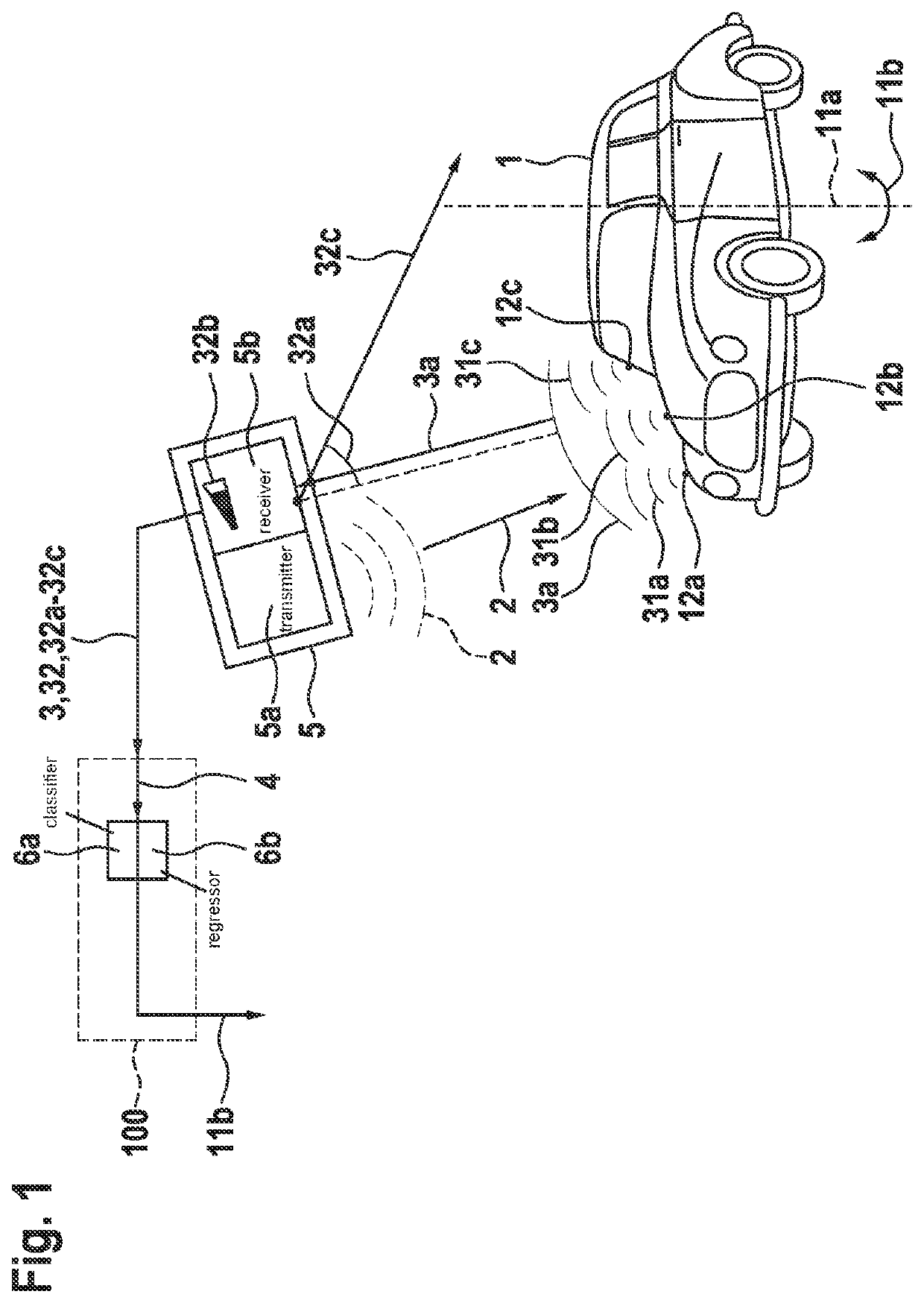
[0049]FIG. 1 shows an exemplary situation in which a large-scale object 1 forms a response 3a to electromagnetic interrogation radiation 2. Used measuring device 5 includes a transmitter 5a for interrogation radiation 2 and a receiver 5b for response 3a of object 1. In the example illustrated in FIG. 1, object 1 is a vehicle which is located in a position 11a and assumes a spatial orientation 11b in the form of a rotational angle in relation to an axis perpendicularly running through object 1. Using various elements (not depicted in FIG. 1), measuring device 5 extracts reflections 32 from the raw data recorded by receiver 5a and outputs these reflections 32 as measuring signal 3. More specifically, at least an angular position 32a, at least an intensity 32b, and at least a distance 32c to the location of reflection 32 are acquired regarding reflections 32.

[0050]With the aid of method 100, spatial orientation 11b of object 1 is analyzed based on measuring signal 3. For this purpose, ...


PUM


Abstract

A method for determining the spatial orientation of an object from at least one measuring signal which includes the response of the object to electromagnetic interrogation radiation. A method for predicting the trajectory of at least one object from at least one measuring signal which includes the response of the object to electromagnetic interrogation radiation, in conjunction with a scalar velocity of the object. A method for training a classifier and / or a regressor.

Description

FIELD[0001]The present invention relates to the detection and monitoring of objects in a detection range based on a response of these objects to electromagnetic interrogation radiation.BACKGROUND INFORMATION[0002]To ensure that a vehicle is able to move in road traffic in an at least partially automated manner, the environment of the vehicle has to be detected and countermeasures have to be initiated if a collision with an object in the environment of the vehicle is looming. The preparation of an environment representation and a localization are also necessary for safe automated driving.[0003]The detection of objects with the aid of radar is independent of the light conditions and, for example, also possible at night at a greater distance without the oncoming traffic being disturbed by the high beam. In addition, the distance and velocity of objects can be directly derived from the radar data. This information is important for the assessment of whether a collision with the objects m...

Claims


Application Information

Patent Timeline
Patent Type & Authority Applications(United States)
IPC IPC(8): G01S13/68G01S7/41G01S13/42G01S13/931
CPCG01S13/68G01S7/415G01S2013/9318G01S13/42G01S13/931G01S7/417G01S13/66G01S13/50G01S7/418
Inventor YANG, CHUNMUENZNER, SEBASTIANTIMM, FABIANEBERT, JASMINKARASZ, ZOLTAN
Owner ROBERT BOSCH GMBH
Features
  • R&D
  • Intellectual Property
  • Life Sciences
  • Materials
  • Tech Scout
  • Unparalleled Data Quality
  • Higher Quality Content
  • 60% Fewer Hallucinations
Learn More