

Connection element for electrically connecting a fluid-coolable individual line, fluid-coolable individual line unit, and charging cable
a technology of connection element and individual line, which is applied in the direction of insulated conductors, cable connections, coupling devices, etc., can solve the problems of hardly being able to grasp, unable to properly handle the cable, and requiring many times the time required to recharge electrically powered vehicles. , to achieve the effect of reducing electrical connection resistance, and increasing mechanical robustness and reliability of compression joints
- Summary
- Abstract
- Description
- Claims
- Application Information
AI Technical Summary
Benefits of technology
Problems solved by technology
Method used
Image

Examples
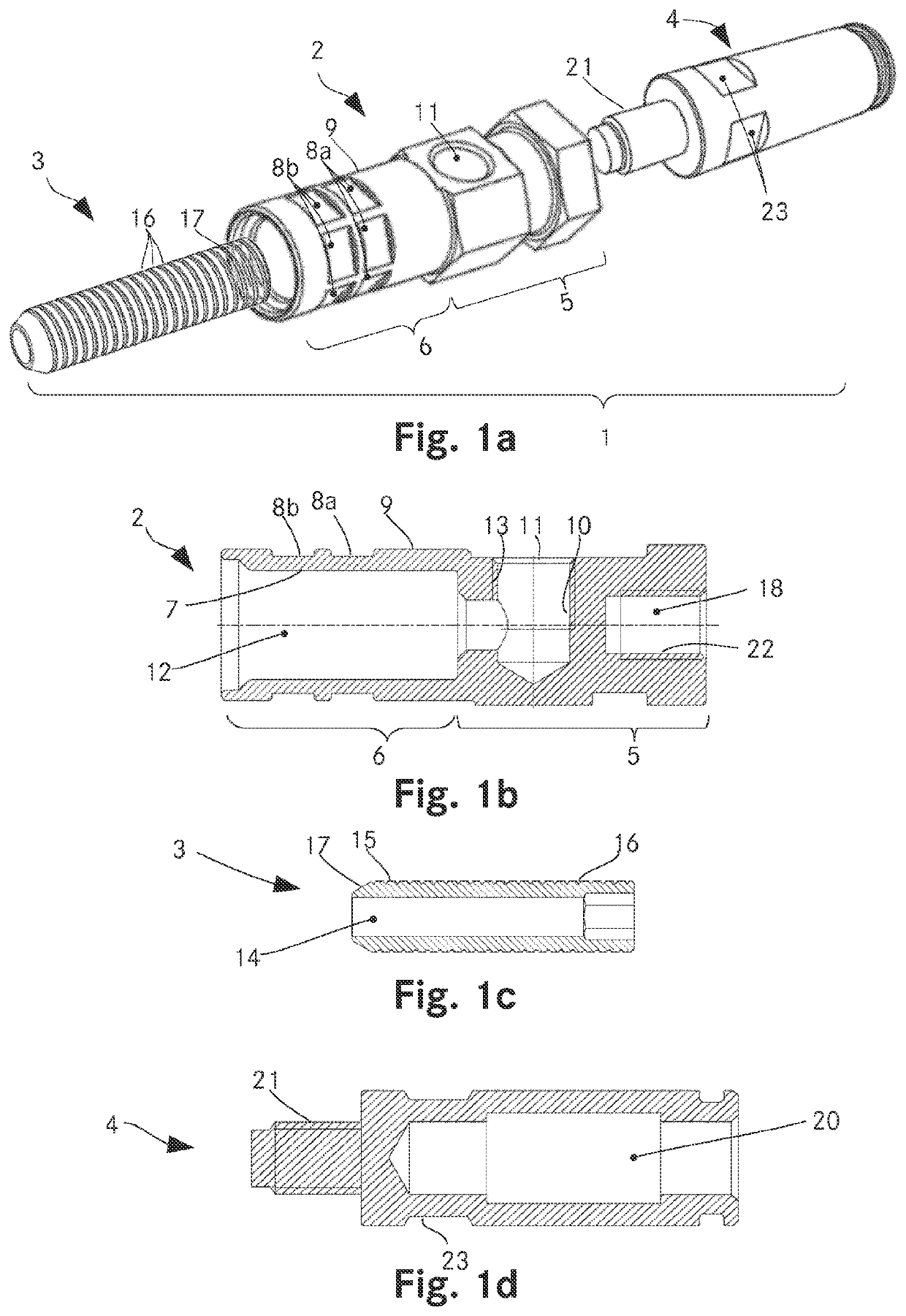
first embodiment
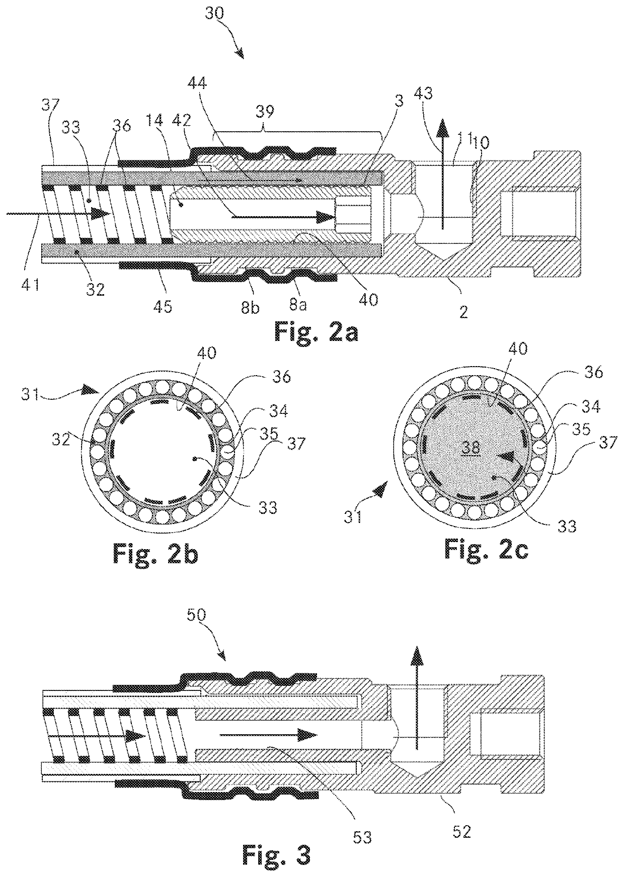
[0084]FIG. 2a shows a detail of an axial section of the inventive fluid-coolable individual line unit, which comprises a connection element according to FIGS. 1a-1d;
[0085]FIG. 2b shows a cross section through the individual line of the fluid-coolable individual line unit according to FIG. 2b;
[0086]FIG. 2c shows the distribution of the cooling fluid in the individual line of FIG. 2b;
second embodiment
[0087]FIG. 3 shows a detail of an axial section of the inventive fluid-coolable individual line unit;
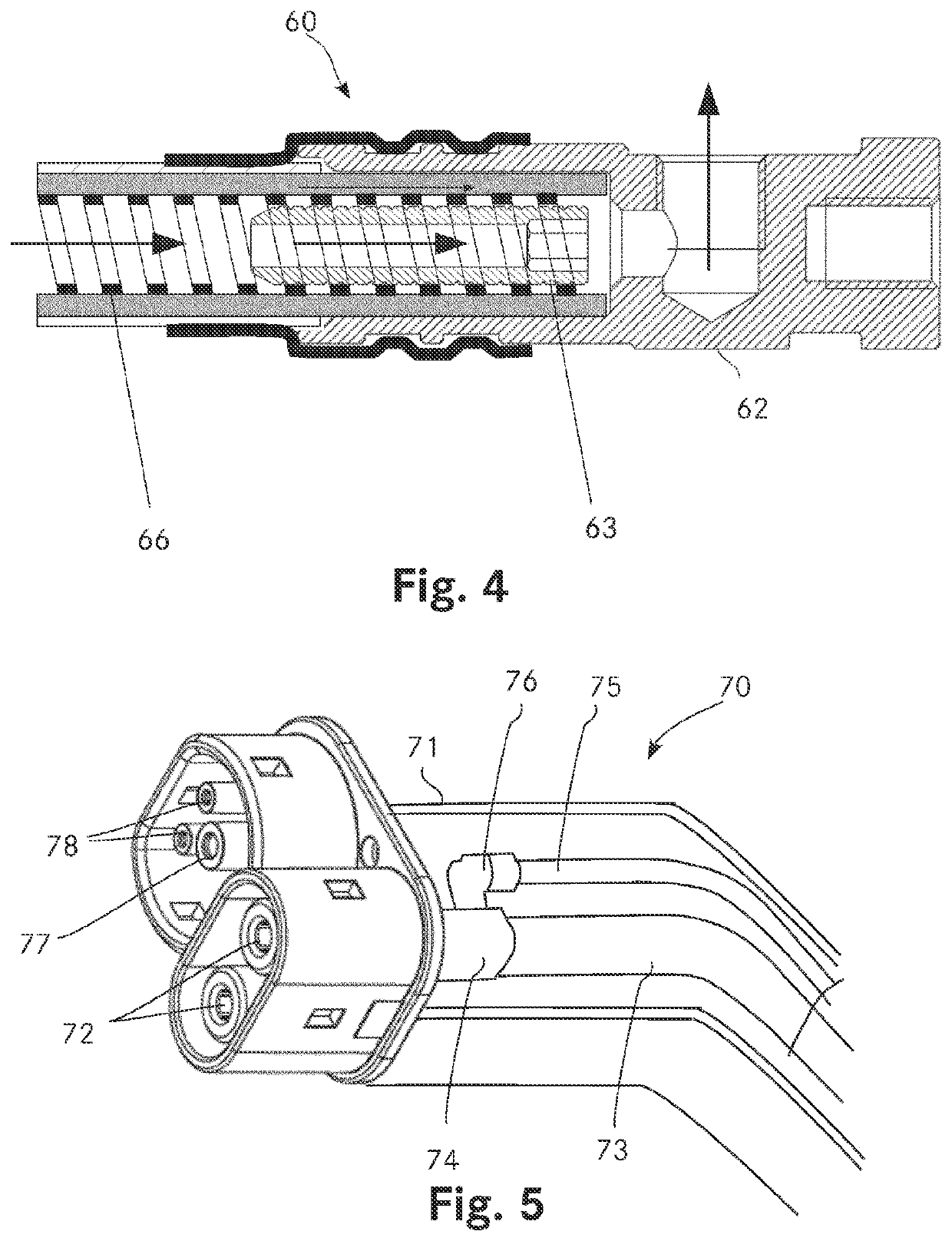
third embodiment
[0088]FIG. 4 shows a detail of an axial section of the inventive fluid-coolable individual line unit;
[0089]FIG. 5 shows an oblique view of a charging plug connector of an inventive DC charging cable;
[0090]FIG. 6 shows a cross section through a charging cable having two individual lines, a neutral conductor, eight signal lines, and two hoses, and
[0091]FIG. 7 shows a schematic illustration of a DC charging cable having two fluid-coolable individual line units and a charging plug connector.
[0092]In principle, identical parts are provided in the figures with the same reference signs.
PUM
| Property | Measurement | Unit |
|---|---|---|
| current | aaaaa | aaaaa |
| currents | aaaaa | aaaaa |
| angle | aaaaa | aaaaa |
Abstract
Description
Claims
Application Information