Liquid ejection head and manufacturing method thereof

Pending Publication Date: 2022-02-03
CANON KK
View PDF0 Cites 0 Cited by
  • Summary
  • Abstract
  • Description
  • Claims
  • Application Information

AI Technical Summary

Benefits of technology

[0004]In the dicing method disclosed in Japanese Patent Application Laid-Open No. 2006-281679, it is not easy to form recesses corresponding to dicing lines at high accuracy in the back surface of a wafer by wet etching. In particular, since the intersection portions of vertical and lateral dicing lines have a complex etching surface, it is extremely difficult to form th

Problems solved by technology

In the dicing method disclosed in Japanese Patent Application Laid-Open No. 2006-281679, it is not easy to form recesses corresponding to dicing lines at high accuracy in the back surface of a wafer by wet etching.
In particular, since the intersection portions of vertical and lateral dicing lines have a complex etching surface, it is extremely difficult to form the r

Method used


Image

  • Liquid ejection head and manufacturing method thereof
  • Liquid ejection head and manufacturing method thereof
  • Liquid ejection head and manufacturing method thereof

Examples


Example

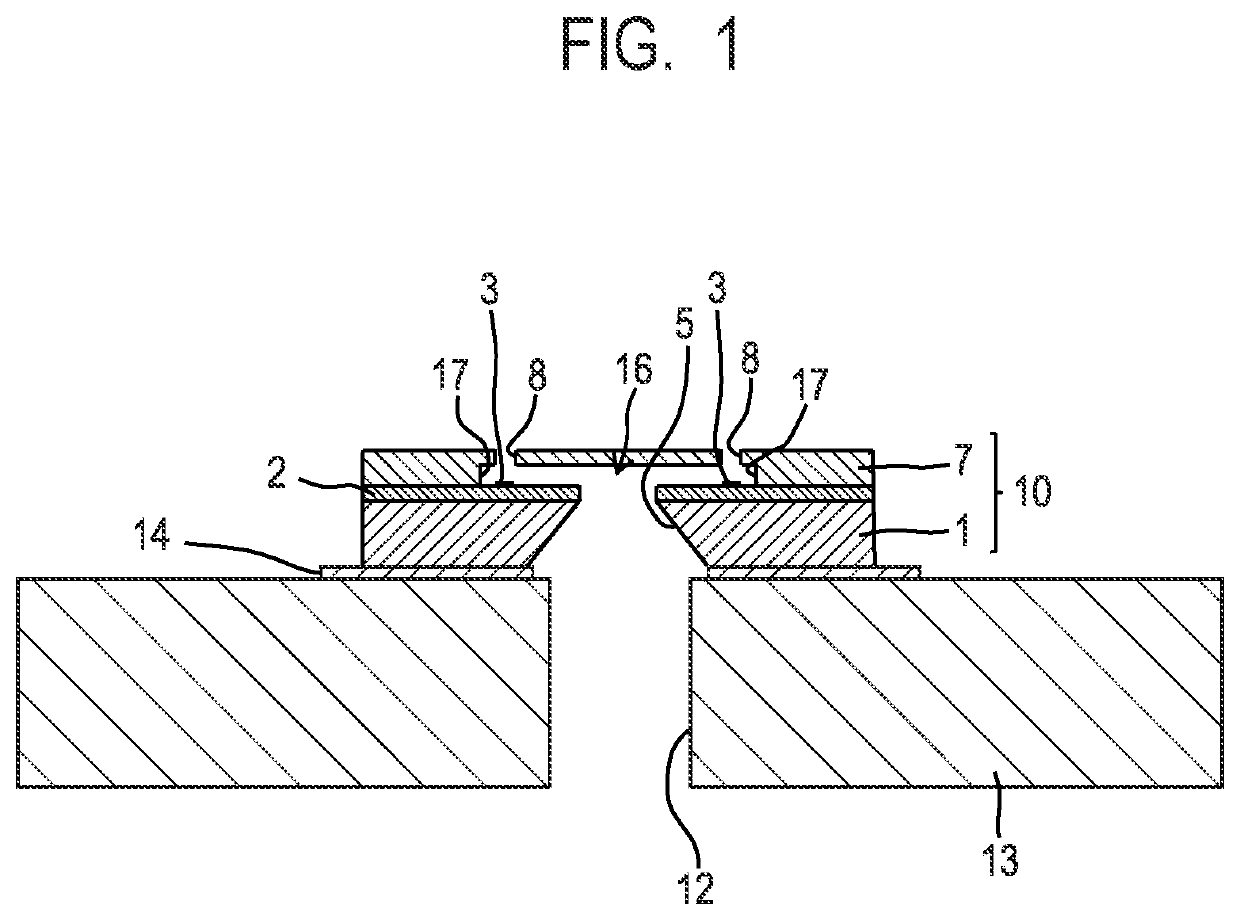
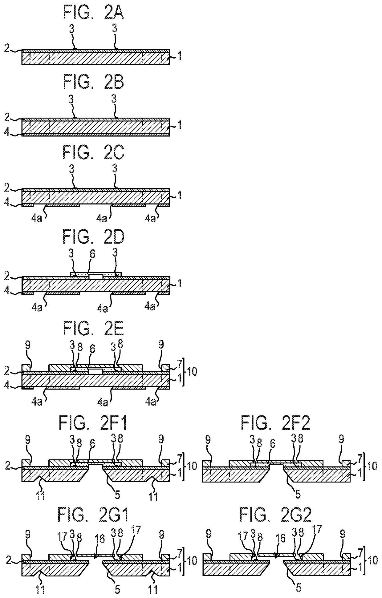
[0015]Preferred embodiments of the present disclosure will be described below with reference to the drawings. In the following description, components having the same function are labeled with the same reference, and duplicated description thereof may be omitted. FIG. 1 is a sectional view illustrating a main part of a liquid ejection head according to the present disclosure. In the basic structure of this liquid ejection head, an element substrate 10 is bound to a support member 13 via an adhesive agent 14. The element substrate 10 has a substrate 1 and an ejection orifice forming member 7. A front layer 2 made of silicon oxide or silicon nitride is formed on one of the surfaces (the upper surface in FIG. 1) of the silicon substrate 1. A liquid supply path 5 that is a through hole is formed in the substrate 1. A predetermined number of energy-generating elements 3 (for example, electro-thermal conversion elements, piezoelectric elements, or the like) that generate energy used for e...


PUM


Abstract

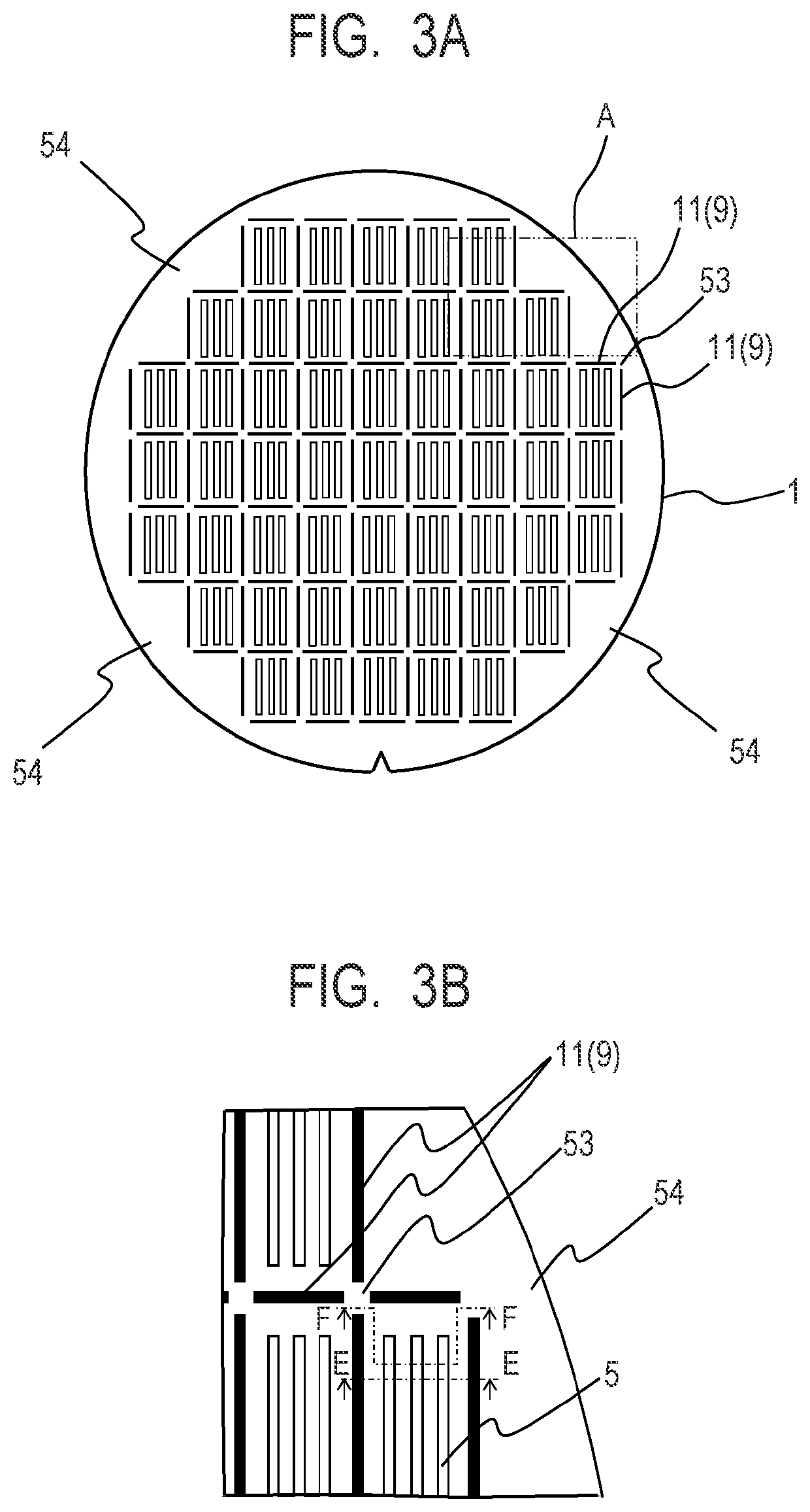
Provided is a manufacturing method of a liquid ejection head, and the manufacturing method includes steps of: providing an ejection orifice forming member on one surface of a wafer, in which an energy-generating element is provided on the one surface of the wafer; forming a recess on the other surface of the wafer; and dicing the wafer along a plurality of dicing lines. The plurality of dicing lines include a dicing line extending in one direction and a dicing line extending in a direction crossing the one direction, and the recess is formed on each of positions overlapping the dicing lines except for an intersection part where the dicing line extending in the one direction intersects the dicing line extending in the direction crossing the one direction.

Description

BACKGROUND OF THE INVENTIONField of the Invention[0001]The present disclosure relates to a liquid ejection head and a manufacturing method thereof.Description of the Related Art[0002]Element substrates of liquid ejection heads such as an inkjet recording head are manufactured by the same manufacturing method as semiconductor substrates. That is, on a wafer whose planar shape is a circle having a diameter of 3 inches to 8 inches (76.2 mm to 203 mm), about several tens to several hundreds of patterns of ejection orifices, energy-generating elements, or the like are formed by a thin film process using a photolithography technology. The wafer is then diced on a pattern basis to obtain a plurality of element substrates. Japanese Patent Application Laid-Open No. H08-281954 proposes a method of dicing a wafer by sand erosion. Since dry films are attached to both sides of a wafer before sand erosion is performed, however, if dicing is performed after ejection orifices or the like are formed...

Claims


Application Information

Patent Timeline
IPC IPC(8): B41J2/16B41J2/14
CPCB41J2/1629B41J2/14201B41J2/1601B41J2/1607B41J2/14016B41J2/1603B41J2/1635B41J2/1632B41J2/1631B41J2/1645B41J2/1623
Inventor HASHIMOTO, YUSUKEIRI, JUNICHIROWATANABE, MAKOTOOJIMA, MASATOMO
Owner CANON KK
Why Eureka
Try Eureka