Eureka AIR delivers breakthrough ideas for toughest innovation challenges, trusted by R&D personnel around the world.

Self-leveling support apparatus

Pending Publication Date: 2022-02-03
O'NEILL +1
View PDF9 Cites 2 Cited by
  • Summary
  • Abstract
  • Description
  • Claims
  • Application Information

AI Technical Summary

Benefits of technology

The invention is about a way to level a table, ladder, or other structure without needing extra sensors, motors, or controls. It works by using a special fluid system that is compressed when the structure is in position, providing stability. The fluid system includes one or more valves that prevent fluid from flowing between the cylinders, and these valves are activated by an increase in pressure or an electronic control system. The main technical effect of this invention is to make it easier to level structures using a simple fluid system and without needing extra equipment or controls.

Problems solved by technology

Landing a helicopter on an uneven surface may create instability during landing and take-off and, in more extreme cases, cause the helicopter blades to contact objects on the ground or the ground itself or may cause the aircraft to tip over onto its side.
A VTOL UAV often faces the same risks as a helicopter when landing on a sloped or uneven surface, but without a pilot on board, or a visual feedback system to assist a remote pilot, to inspect the surface and make adjustments or choose another location, the risks faced by the UAV are greater than those of a manned aircraft.
Specifically, the landing areas available to a VTOL UAV may be more limited, and therefore its utility may likewise be significantly limited.
If a VTOL UAV tips over during landing or comes to rest at an angled position, it may not be able to perform its intended function or to resume flight without operator intervention, often at significant cost or delay.
Active systems also require a power source that can add weight and cost.
Restaurant tables frequently become unstable and tilt when loaded or pressed upon.
This instability occurs because the four (or more) feet of the table do not all rest on the floor with equal fit, either because the floor is not flat or the feet are not positioned properly.

Method used


Image

  • Self-leveling support apparatus
  • Self-leveling support apparatus
  • Self-leveling support apparatus

Examples


Embodiment Construction

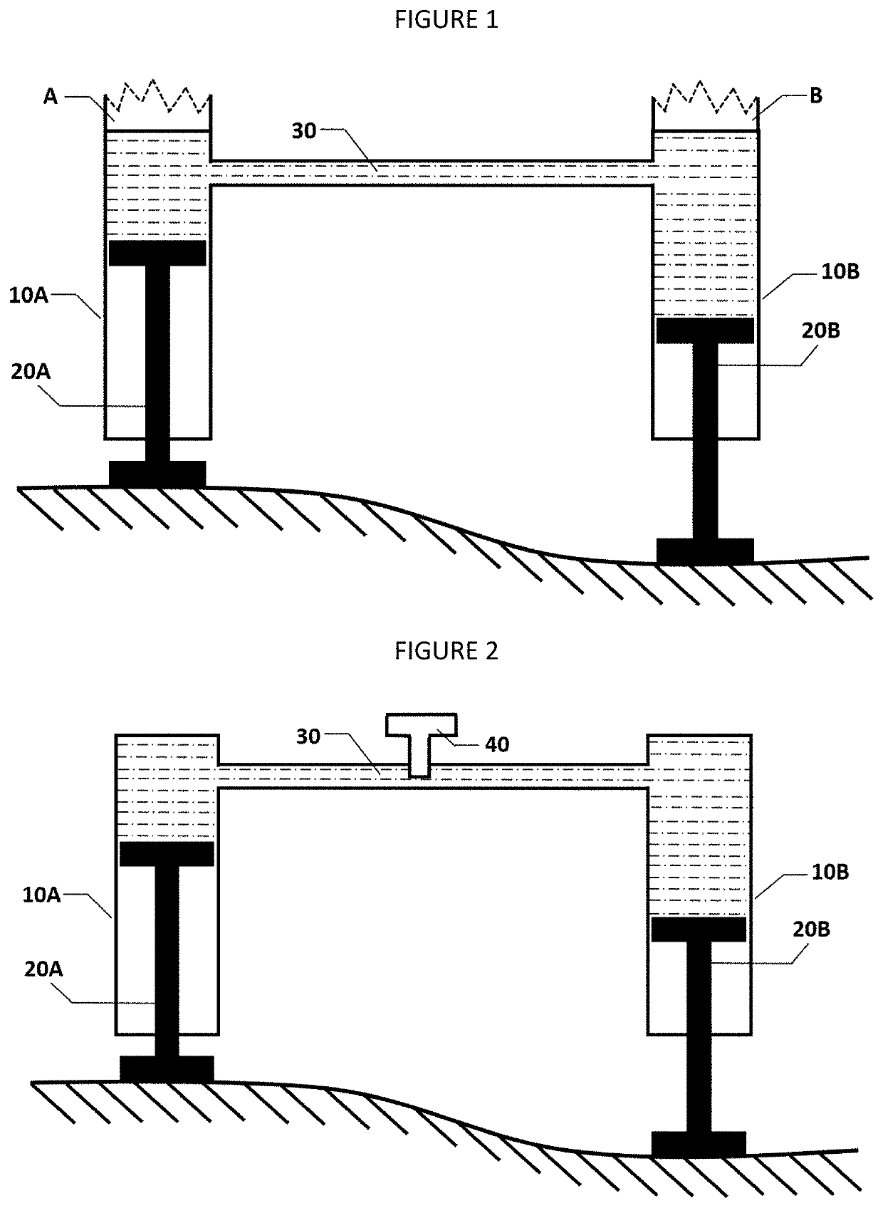
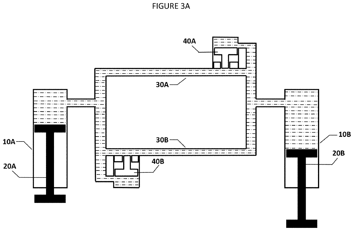
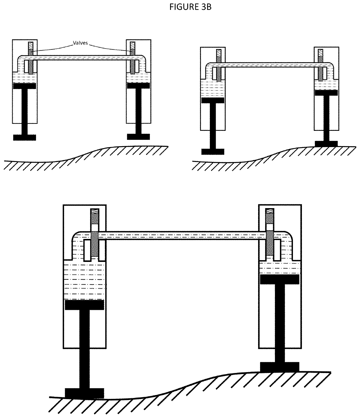
[0022]Referring now to the drawings wherein the showings are for purposes of illustrating embodiments of the self-leveling support device (the “invention”) only and not for purposes of limiting the same, and wherein like reference numerals are understood to refer to like components.

[0023]With reference to FIG. 1, leg A and leg B of the unit being supported (i.e., the UAV, table, ladder, etc., (“unit”)) are each fitted with a cylinder comprising a housing 10A / 10B, a piston rod 20A / 20B. A line 30 that comprises either a flexible tube or rigid channel connects the cylinders. A fluid is disposed within the reservoir formed by line 30 and cavities bounded by the cylinder housings 10A / 10B and the upper ends of piston rods 20A / 20B. The fluid fully occupies the reservoir within the line 30 and the cylinder cavities and is allowed to flow freely through the line 30 and within the cylinders such that compression of piston rod 20A produces an elongation of piston rod 20B and vice versa. The fl...


PUM


Abstract

Provided is a self-leveling support apparatus for use with a UAV or stationary device such as a table or ladder, the apparatus having multiple leg members, each associated with a hydraulic or pneumatic cylinder; a connection among the hydraulic or pheumatic cylinders such that they share a common reservoir of fluid; a locking mechanism that obstructs free flow of fluid among the cylinders and stabilizes the UAV or stationary device without the need for electronic sensors or control systems.

Description

CROSS-REFERENCE TO RELATED APPLICATION[0001]This application claims the benefit of U.S. Provisional Application No. 63 / 059,570, filed Jul. 31, 2020, the entirety of which is fully incorporated by reference herein.TECHNICAL FIELD[0002]The present invention relates to a passive self-leveling support apparatus and various embodiments. More particularly, the present invention relates to landing gear for unmanned aerial vehicles with additional application for tables, ladders, or other devices that could benefit from a simple self-leveling mechanism.BACKGROUND[0003]Unmanned aerial vehicles (“UAVs”) comprise any aerial vehicle that is either piloted remotely or controlled by means of an onboard control system without human intervention. UAVs may be used to perform military, scientific, photographic, or other functions without direct risk to human life or where alternative means for performing that function would be impracticable. For example, the U.S. military has used UAVs to carry out a...

Claims


Application Information

Patent Timeline
IPC IPC(8): B64F1/12
CPCB64F1/12B64C39/024B64C2025/008A47B91/16B64U60/50B64U10/20
Inventor O'NEILLFLEMING, JONATHAN
Owner O'NEILL
Why Eureka
Eureka Blog
Learn More