
Control system for hybrid vehicle

a control system and hybrid technology, applied in the direction of propulsion parts, external condition input parameters, transportation and packaging, etc., can solve the problems of sudden motor stop, insufficient torque generated by the engine in the lean-burn mode, and inability to supply electricity from the battery to the motor, so as to prevent sudden reduction of the speed of the hybrid vehicle

Inactive Publication Date: 2022-02-10
TOYOTA JIDOSHA KK
View PDF0 Cites 2 Cited by
  • Summary
  • Abstract
  • Description
  • Claims
  • Application Information

AI Technical Summary

Benefits of technology

The present invention provides a control system for a hybrid vehicle that prevents a sudden reduction in motor output torque during high load operations. This is achieved by restricting the upper limit of the electric storage device's output power based on factors such as distance of the load, altitude, and total weight. This prevents the vehicle from being out of charge and maintains the motor's output power. The invention also prevents sudden reduction in speed and drive force of the vehicle, leading to improved driver safety and comfort.

Problems solved by technology

However, although a fuel consumption may be reduced, a torque generated by the engine will be insufficient in the lean-burn mode.
However, if the state of charge level of the battery falls to a lower limit level as a result of supplying electricity to the motor from the battery, the electricity can no longer be supplied from the battery to the motor and the motor will stop suddenly.
For instance, when the vehicle climbs an hill while depressing an accelerator pedal deeply or travels while towing a mobile home, an electric consumption to generate the assist torque by the motor is increased significantly and the state of charge level of the battery will fall to the lower limit level promptly.
As a result, the motor may stop suddenly and the drive torque to propel the vehicle may drop significantly.
That is, the drive torque to propel the vehicle will drop undesirably irrespective of an operation carried out by the driver, and hence a speed of the vehicle may not be maintained to a desired speed.
For example, the upper limit of the output power of the electric storage device is restricted when the hybrid vehicle tows an object such as a mobile home or when the hybrid vehicle travels on a road higher than the threshold level.

Method used


Image

  • Control system for hybrid vehicle
  • Control system for hybrid vehicle
  • Control system for hybrid vehicle

Examples


Embodiment Construction

)

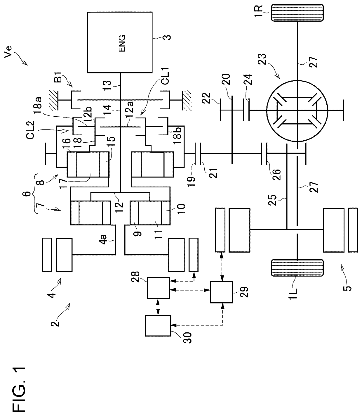
[0038]An exemplary embodiment of the present disclosure will now be explained with reference to the accompanying drawings. Referring now to FIG. 1, there is shown one example of a structure of a hybrid vehicle (as will be simply called the “vehicle” hereinafter) Ve to which the control system according to the exemplary embodiment of the present disclosure is applied. Specifically, FIG. 1 shows a drive unit 2 of the vehicle Ve that drives a pair of front wheels 1R and 1L, and the drive unit 2 comprises an engine (referred to as “ENG” in the drawings) 3 as a main prime mover, a first motor (referred to as “MG1” in the drawings) 4, and a second motor (referred to as “MG2” in the drawings) 5. According to the exemplary embodiment, a motor-generator having a generating function is adopted as the first motor 4. In the vehicle Ve, a speed of the engine 3 is controlled by the first motor 4, and the second motor 5 is driven by electric power generated by the first motor 4 to generate a driv...


PUM


Abstract

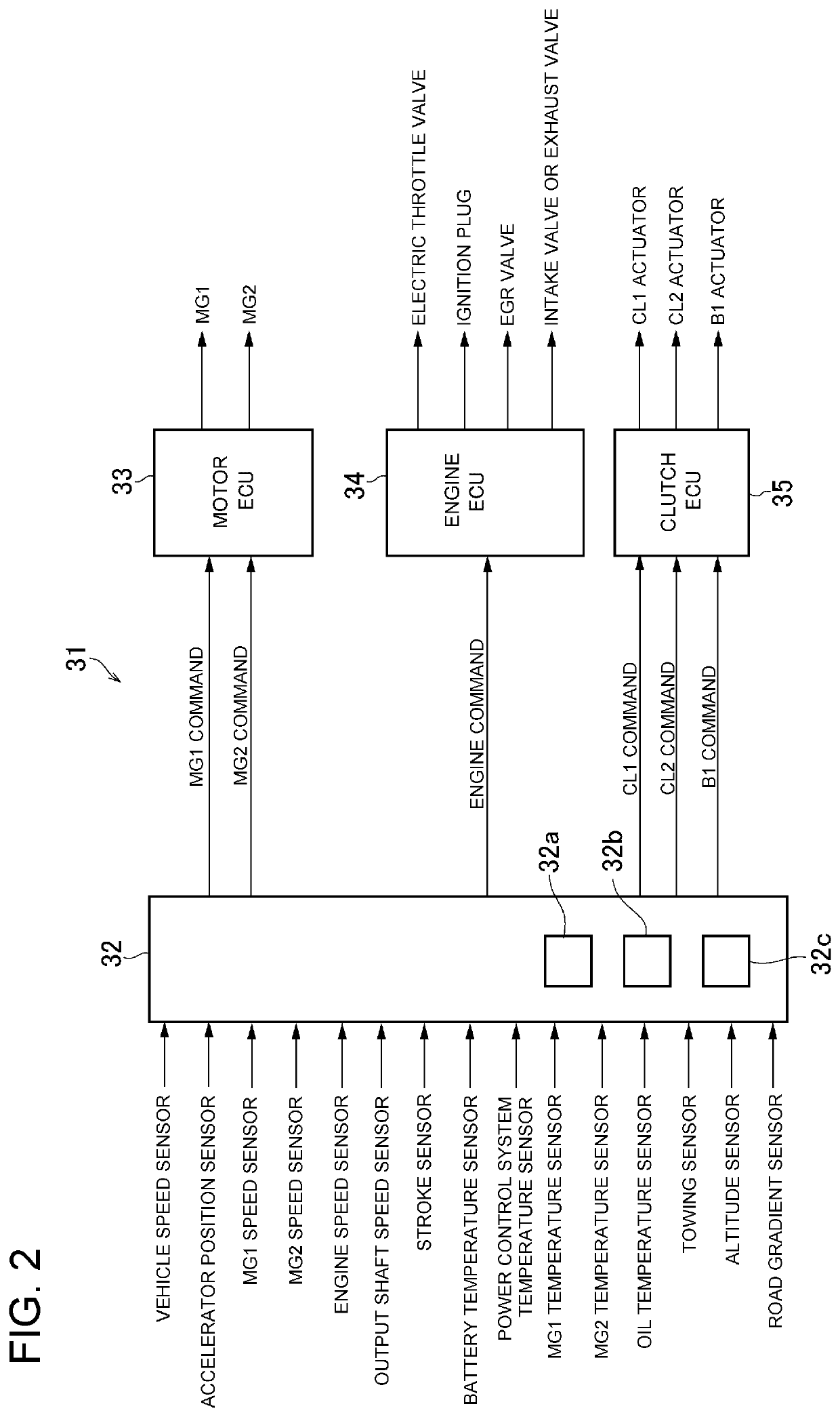
A control system for a hybrid vehicle configured to avoid a sudden and significant reduction in a drive torque generated by a motor during high load operation. A controller comprises a determiner that determines a satisfaction of a predetermined condition, and a power limiter that restricts an upper limit of an output power of an electric storage device supplied to the motor upon satisfaction of the predetermined condition, to a restricted upper limit value which is smaller than a normal upper limit value set in a case that the predetermined condition is not satisfied.

Description

CROSS-REFERENCE TO RELATED APPLICATIONS[0001]The present disclosure claims the benefit of Japanese Patent Application No. 2020-134664 filed on Aug. 7, 2020 with the Japanese Patent Office, the disclosures of which are incorporated herein by reference in its entirety.BACKGROUNDField of the Disclosure[0002]Embodiments of the present disclosure relate to the art of a control system for a hybrid vehicle in which a prime mover includes an engine and a motor, and more especially, to a control system for controlling an output torque of the motor under high load operation.Discussion of the Related Art[0003]JP-B2-4075959 describes a control system for a hybrid vehicle having an engine and a motor as a prime mover. The control system taught by JP-B2-4075959 is configured to operate the engine in the lean-burn mode in which an air / fuel ratio is higher than that in the stoichiometric mode. However, although a fuel consumption may be reduced, a torque generated by the engine will be insufficient...

Claims


Application Information

Patent Timeline
IPC IPC(8): B60W20/20B60K6/26B60K6/36B60K6/387
CPCB60W20/20B60K6/26B60K6/36B60K6/387B60W2710/242B60W2710/08B60W2510/0638B60W2552/15B60W2555/40B60W2530/10B60W2510/244B60W2510/0657B60W2530/203B60W10/26B60W10/08B60W20/00B60K6/445B60W2710/248B60W20/13B60W20/10B60W10/06B60W2530/207B60W2520/10B60W2540/10B60W30/182B60W30/1882B60W2050/0026B60K6/365B60K2006/381Y02T10/62Y02T10/70
Inventor IMAMURA, TATSUYA
Owner TOYOTA JIDOSHA KK
Learn More