Unlock instant, AI-driven research and patent intelligence for your innovation.

Method and apparatus for contactless high-resolution determination and control of an object position

a high-resolution, object-positioning technology, applied in the direction of instruments, measurement devices, using optical means, etc., can solve the problems of not being able to achieve the optimal design of high-vacuum or ultra-high-vacuum vacuum chambers, and the application of such measurement tools to control the position of objects in vacuum chamber systems is problemati

Active Publication Date: 2022-02-10
NEOCERA
View PDF13 Cites 0 Cited by
  • Summary
  • Abstract
  • Description
  • Claims
  • Application Information

AI Technical Summary

Benefits of technology

This patent describes a new method and apparatus for detecting and controlling small movements of objects using optics. The system overcomes shortcomings of conventional systems by using a specific mirror arrangement to capture images of sufficient quality. The method also takes into account factors that may cause surface shifts and ensures the electron beam impact point remains stable for an extended time. The technical effects of this patent are improved precision in detecting and controlling small movements of objects using optics.

Problems solved by technology

However, the optical triangulation approach does not typically examine the position of the actual laser beam spot on the object's surface of interest relative to other objects.
Disadvantageously, application of such measurement tools to control a position of objects in vacuum chamber systems is problematic, as it would require either a single window of an impractically large size (for example, exceeding 150 mm in diameter), or a system with two separate chamber optical windows (one for the diode laser input and another for the reflected light output), which is not an optimal design for high-vacuum (HV) or ultra high-vacuum (UHV) vacuum chambers.
Many of those tools operate within HV (high vacuum) or UHV (ultra high-vacuum) systems, where acceptable options for suitable positioning instrumentation are limited.

Method used


Image

  • Method and apparatus for contactless high-resolution determination and control of an object position
  • Method and apparatus for contactless high-resolution determination and control of an object position
  • Method and apparatus for contactless high-resolution determination and control of an object position

Examples


Embodiment Construction

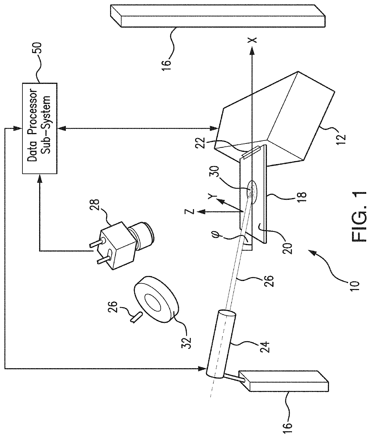
[0106]Referring to FIGS. 1-5, the present system 10 is adapted for determining a position, as well as a shift in position, of an object 12. Particularly, in the depicted arrangement, the subject system 10 is adapted for determining and control of the position, as well as a shift of position, of the object 12 along the direction corresponding to the Z-axis.

[0107]The system 10 includes one or more of bases 16 which are stationary objects relative to which the position (displacement, shift, or drift) of the object 12 is determined and controlled in accordance with the principles of the present methodology, as will be detailed infra.

[0108]The system 10 further includes a screen member 18 (also referred to herein as a laser beam screen). The screen member 18 has a surface 20 to which the Z-axis is substantially normal.

[0109]A link 22 is formed between the object 12 and the surface 20 of the screen member 18. The link 22 is a rigid link which constitutes an interface between the object 12...


PUM


Abstract

A high-sensitivity optical system to determine and / or control spatial displacement and position of objects applicable to various situations when a contact measurement cannot be performed, such as in high-vacuum or ultra-high vacuum chambers, at high temperatures, in aggressive chemical environments, etc. A laser beam is directed at a low glancing angle to a screen secured to an object. The screen's surface is normal to a motion direction of interest. A location of the bright laser beam spot on the screen surface is acquired and the displacement thereof is analyzed and quantified based on the change in distance from the laser beam spot to a reference element which is arranged on the screen and creates a variation in the acquired image brightness. A feedback loop control mechanism is provided which returns the displaced object to its original position.

Description

REFERENCE TO RELATED PATENT APPLICATION(S)[0001]This Utility Patent Application is a National Stage Application of PCT / US2019 / 065428 filed on 10 Dec. 2019 which is based on Provisional Patent Application No. 62 / 777,498 filed on 10 Dec. 2018.FIELD OF INVENTION[0002]The present invention relates to a method and a system adapted to determine and control the position of an object.[0003]Specifically, the present invention is directed to detection and control of small displacement of objects respective to stationary reference objects.[0004]More specifically, the present invention relates to a high-resolution contactless positioning technique to determine and / or to control spatial location of objects in situations when mechanical measurements cannot be conducted using contact measurement methods, such as, for example, for processes conducted within High-Vacuum (HV) or Ultra-High-Vacuum (UHV) chambers, as well as at high temperature or aggressive chemical environments, etc.BACKGROUND AND PR...

Claims


Application Information

Patent Timeline
Patent Type & Authority Applications(United States)
IPC IPC(8): G01B11/02G01B11/03G01B11/14
CPCG01B11/026G01B11/14G01B11/03
Inventor STRIKOVSKI, MIKHAIL D.GARRAHAN, STEVEN L.PARKINSON, JONATHAN E.KIM, JEONGGOOKOLAGANI, SOLOMON
Owner NEOCERA