
Apparatus and method for compressing ray tracing acceleration structure build data

a technology of acceleration structure and build data, applied in the field of graphics processors, can solve the problems of requiring a significant amount of time on a conventional general-purpose processor, ai denoising is still a costly operation, and a large amount of computational effort in the training process

Pending Publication Date: 2022-02-17
INTEL CORP
View PDF0 Cites 2 Cited by
  • Summary
  • Abstract
  • Description
  • Claims
  • Application Information

AI Technical Summary

Benefits of technology

The patent text describes an invention related to the field of graphics processors. More specifically, it describes an apparatus and method for compressing ray tracing acceleration structure build data. The technical effect of this invention is to improve the efficiency of ray tracing in graphics processing by reducing the amount of data needed to be processed, which can lead to faster and more resource-intensive performance.

Problems solved by technology

AI denoising is still a costly operation and as gaming moves into the cloud.
The training process can be computationally intensive and may require a significant amount of time on a conventional general-purpose processor.
Deeper neural networks are generally more computationally intensive to train.
However, the additional hidden layers of the network enable multistep pattern recognition that results in reduced output error relative to shallow machine learning techniques.
Not all CNN implementations make use of fully connected layers.
Additionally, some CNN implementations do not include a pooling stage.
Whether supervised or unsupervised, the training process for particularly deep neural networks may be too computationally intensive for a single compute node.
Distributed training has increased overhead relative to training on a single machine.
One of the difficulties with a distributed architecture is the large amount of packetized data that must be transmitted between each of the ray tracing nodes 3610-3613.
A performance limitation of hybrid ray tracing traversal architectures is the overhead of launching traversal queries from the execution units and the overhead of invoking programmable shaders from the ray tracing hardware.
A variety of other scenarios may cause data access divergence.
That, however, breaks up SIMD / SIMT groups.
However, there is an overhead associated with the messaging between the SIMD / SIMT cores / execution units 4001 (sometimes simply referred to herein as SIMD / SIMT processors or cores / EUs) and the MIMD traversal / intersection unit 4005.
Furthermore, the sorting unit 4008 may not extract perfect SIMD / SIMT utilization from incoherent shader calls.
Most of the performance overhead is caused by these two context switches every time when the shader invocation is necessary during single-ray traversal.
There is also a setup cost that needs to be performed before first traversal step on the BVH.
The main problem with this approach is that there is no upper bound of any-hit shader invocations.
A challenge for potential implementations is that it is not trivial to guarantee the execution order of hit shaders (the standard “roundtrip” approach guarantees that the hit shader of the closest intersection is executed first, etc.).
This may be problematic for intersection shaders because the rest of the BVH traversal depend on the result of all dispatched intersection tests.
This means that a synchronization operation is necessary to wait for the result of the shader invocations, which can be challenging on asynchronous hardware.
Without these stochastic techniques, the transition between LODs can result in distracting artifacts where objects suddenly change in appearance when a new LOD is selected.
These 8-bit masks and the associated bit-wise logic operations result in limited LOD transition capabilities.
As these arrays are often of considerable size, this process is bandwidth-intensive.
Thus, improvements in BVH build compute performance, such as could be expected from a hardware BVH builder, are likely to have only a limited impact if this bandwidth issue is not addressed.
However, when AABB compression leads to a variable number of AABBs per cache line, the AABB compression block storing a given primitive is not easily determined after compression.
Storing conventional indices is therefore not compatible with the AABB Compression Blocks described herein.
In fact, although HBI indices provide compression, the worst-case situation can actually result in an expansion of the index data (up to an upper bound).
However, the embodiments of the invention described herein result in a new challenge in that a list of Index Compression Blocks must be partitioned rather than a list of indices.
Moreover, it is not possible to predict the number of blocks until after all of the indices are compressed.
As the AABBs are not recompressed at each level of the build, it is difficult to incorporate spatial splits which occur during the build itself (as is seen in some related works) into the compression scheme.

Method used


Image

  • Apparatus and method for compressing ray tracing acceleration structure build data
  • Apparatus and method for compressing ray tracing acceleration structure build data
  • Apparatus and method for compressing ray tracing acceleration structure build data

Examples


example neural

Network Implementations

[0286]There are many types of neural networks; a simple type of neural network is a feedforward network. A feedforward network may be implemented as an acyclic graph in which the nodes are arranged in layers. Typically, a feedforward network topology includes an input layer and an output layer that are separated by at least one hidden layer. The hidden layer transforms input received by the input layer into a representation that is useful for generating output in the output layer. The network nodes are fully connected via edges to the nodes in adjacent layers, but there are no edges between nodes within each layer. Data received at the nodes of an input layer of a feedforward network are propagated (i.e., “fed forward”) to the nodes of the output layer via an activation function that calculates the states of the nodes of each successive layer in the network based on coefficients (“weights”) respectively associated with each of the edges connecting the layers. ...

examples

[0665]The following are example implementations of different embodiments of the invention.

[0666]Example 1. An apparatus comprising: traversal hardware logic to traverse rays through a graphics scene comprising a plurality of primitives; and an acceleration data structure processing unit comprising: a bounding box compressor to compress a set of bounding boxes to generate a plurality of bounding box compression blocks, an index compressor to compress a set of indices to generate a plurality of index compression blocks, and an acceleration data structure builder to process the bounding box compression blocks and index compression blocks to generate acceleration data structures

[0667]Example 2. The apparatus of example 1 wherein the acceleration data structure comprises a bounding volume hierarchy (BVH) to be used by the traversal hardware logic to traverse the rays through the graphics scene, the bounding boxes of the BVH stored as a number of axis-aligned bounding boxes (AABBs) compri...


PUM


Abstract

Apparatus and method for compression of acceleration structure build data in a ray tracing implementation. For example, one embodiment of an apparatus comprises: traversal hardware logic to traverse rays through a graphics scene comprising a plurality of primitives; and an acceleration data structure processing unit comprising: a bounding box compressor to compress a set of bounding boxes to generate a plurality of bounding box compression blocks, and an index compressor to compress a set of indices to generate a plurality of index compression blocks, and an acceleration data structure builder for constructing acceleration structures based on bounding box compression blocks and index compression blocks

Description

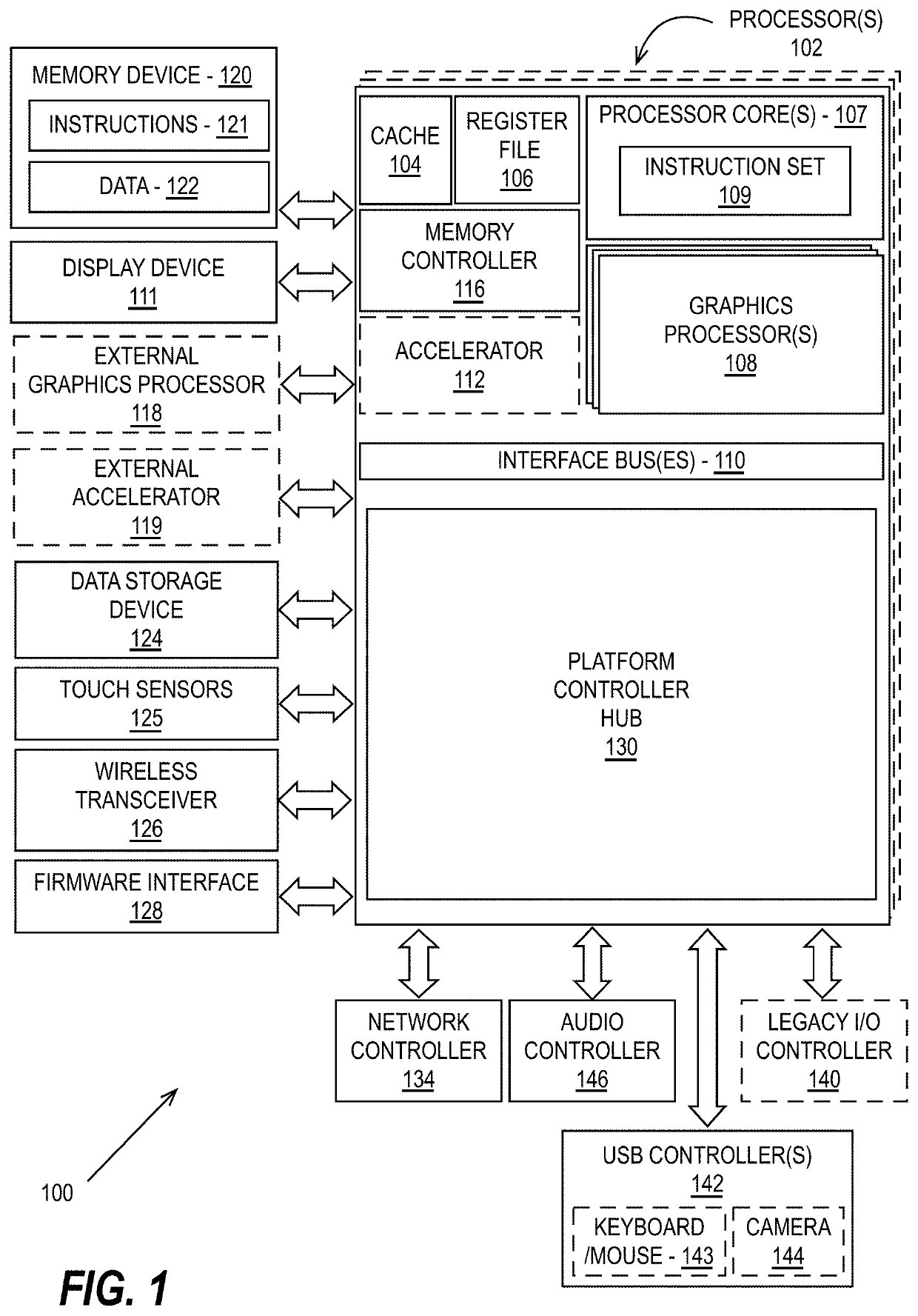
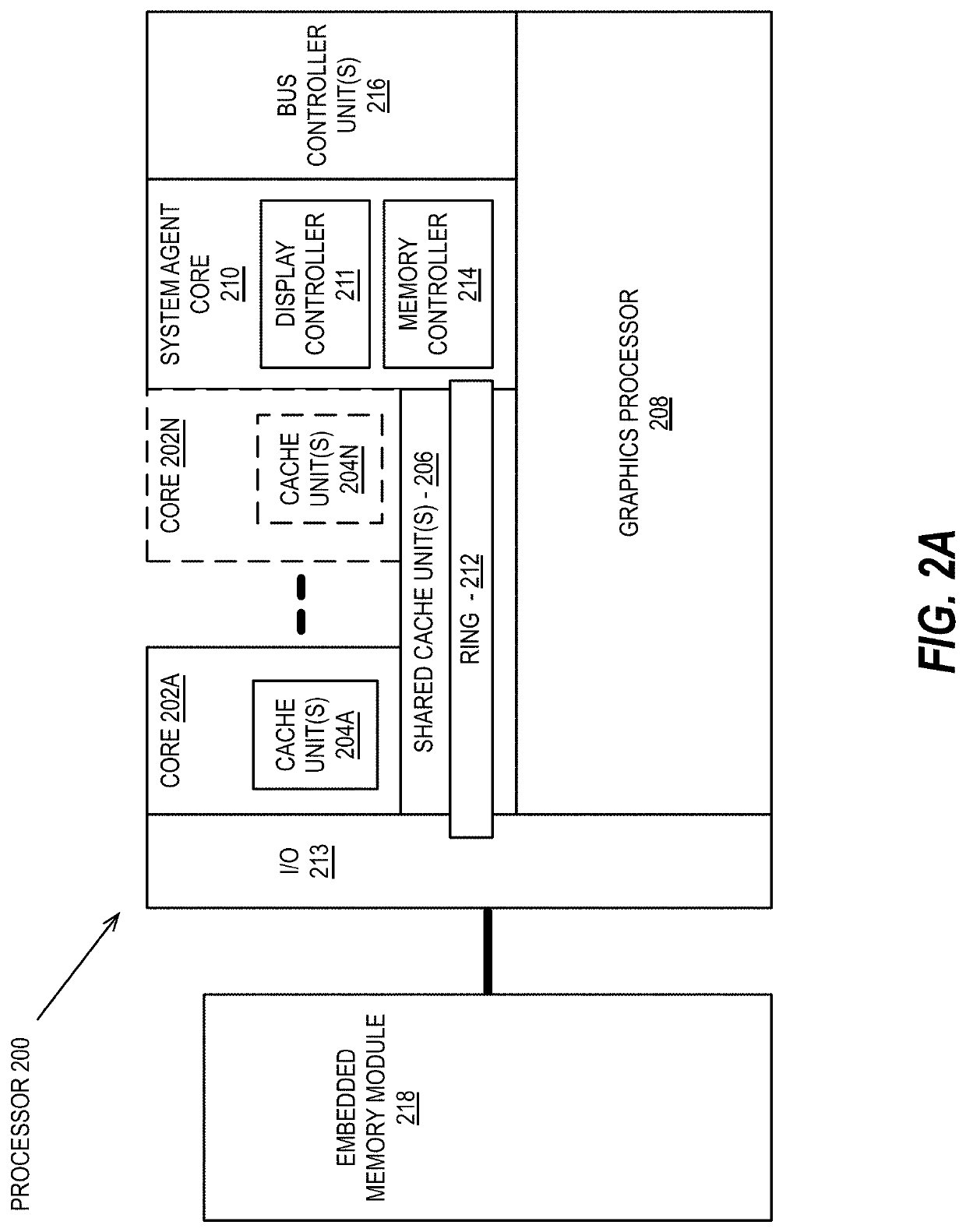
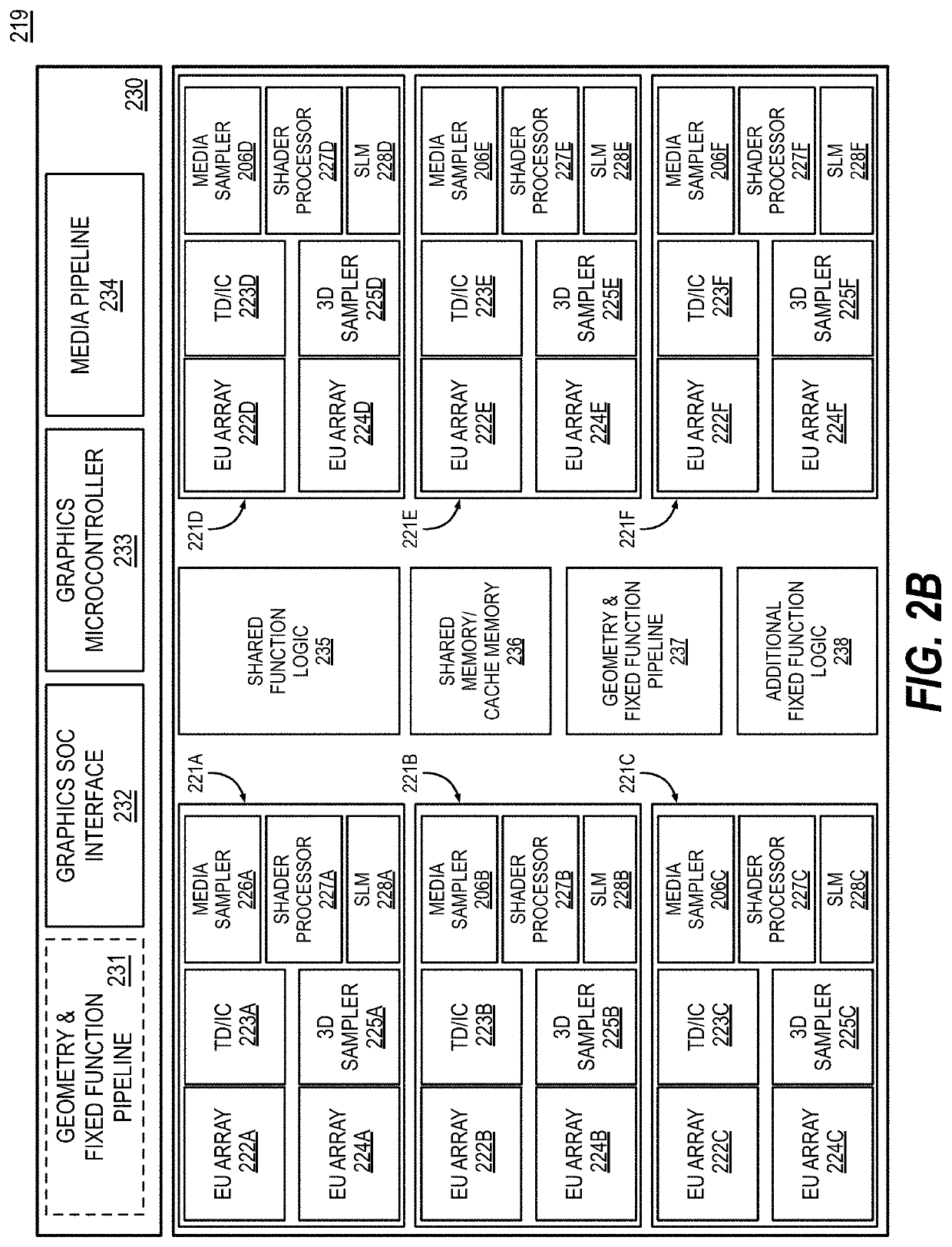
CROSS REFERENCE TO RELATED APPLICATIONS[0001]This application claims the benefit of co-pending U.S. Provisional Application No. 63 / 066,799, filed Aug. 17, 2020, all of which is herein incorporated by reference.BACKGROUNDField of the Invention[0002]This invention relates generally to the field of graphics processors. More particularly, the invention relates to an apparatus and method for compressing ray tracing acceleration structure build data.Description of the Related Art[0003]Ray tracing is a technique in which a light transport is simulated through physically-based rendering. Widely used in cinematic rendering, it was considered too resource-intensive for real-time performance until just a few years ago. One of the key operations in ray tracing is processing a visibility query for ray-scene intersections known as “ray traversal” which computes ray-scene intersections by traversing and intersecting nodes in a bounding volume hierarchy (BVH).BRIEF DESCRIPTION OF THE DRAWINGS[0004]...

Claims


Application Information

Patent Timeline
Patent Type & Authority Applications(United States)
IPC IPC(8): G06T15/06G06T15/08G06T15/00G06T17/10G06T9/00G06T1/20
CPCG06T15/06G06T15/08G06T15/005G06T2210/12G06T9/00G06T1/20G06T17/10G06N20/00G06F9/5016G06T9/001G06T17/20G06T3/4007
Inventor DOYLE, MICHAELKOTHANDARAMAN, SREENIVAS
Owner INTEL CORP
Learn More