Display panel and display device including the same

a technology of display panel and display device, which is applied in the field of display panel, can solve the problems of reducing the width of the fan-out area, placing limits, etc., and achieves the effects of reducing the width of the dead space, preventing or reducing the contact failure between the signal pad and the signal terminal

Pending Publication Date: 2022-02-24
SAMSUNG DISPLAY CO LTD
View PDF3 Cites 1 Cited by
  • Summary
  • Abstract
  • Description
  • Claims
  • Application Information

AI Technical Summary

Benefits of technology

[0008]Aspects of some example embodiments of the present inventive concept also include a display panel in which contact failure between signal pads and signal terminals is relatively reduced.
[0017]According to some embodiments, a distance in the first direction between the side of the display area and a first end of each of the (k)th to (n)th signal pads gradually decreases.
[0031]The display panel according to some embodiments may include the signal pads that gradually increase in length outwardly from the central portion of the pad area. Accordingly, width of the fan-out area may be relatively reduced. Therefore, it is possible to implement a narrow bezel by reducing the width of the dead space.
[0032]The display device according to some embodiments may include the signal pads spaced apart from each other in a direction perpendicular to the length direction, and the signal terminals overlapping corresponding ones of the signal pads, respectively. Therefore, even in a large display device in which a plurality of driving integrated circuits are used, contact failure between the signal pads and the signal terminals may be prevented or reduced.

Problems solved by technology

However, as the number of fan-out lines connected to one driving integrated circuit increases, and as the number of driving integrated circuits used in a display panel increases due to large display devices, limits may be placed on the amount that the width of the fan-out area can be reduced.

Method used


Image

  • Display panel and display device including the same
  • Display panel and display device including the same
  • Display panel and display device including the same

Examples


Embodiment Construction

[0045]Illustrative, non-limiting example embodiments will be more clearly understood from the following detailed description in conjunction with the accompanying drawings.

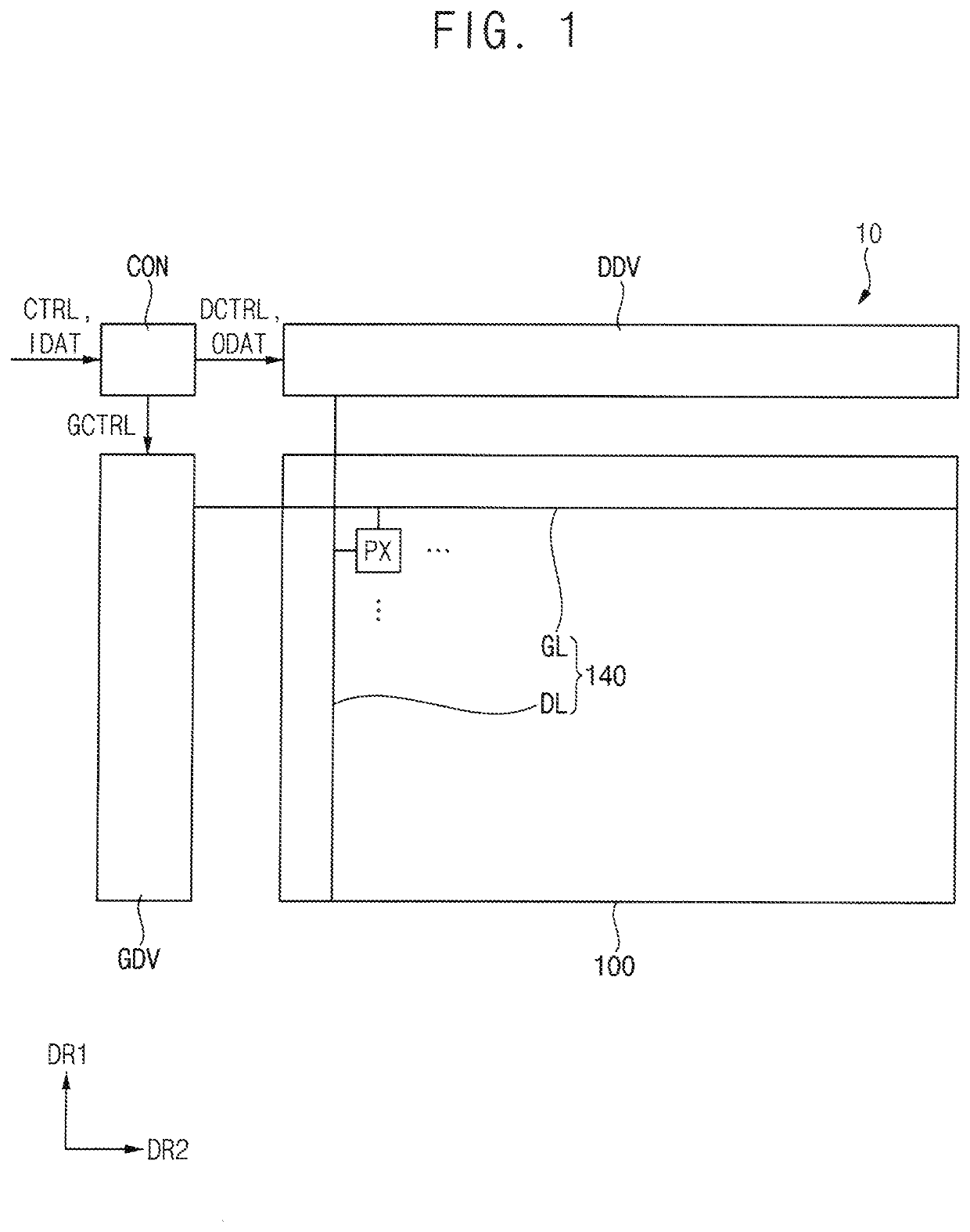
[0046]FIG. 1 is a block diagram illustrating a display device according to some embodiments.

[0047]Referring to FIG. 1, a display device 10 may include a display panel 100 and a panel driver. The panel driver may include a driving controller CON, a gate driver GDV, and a data driver DDV.

[0048]The display panel 100 may include a plurality of pixels PX and a plurality of signal lines 140 electrically connected to the pixels PX. The signal lines 140 may include gate lines GL and data lines DL. For example, each of the data lines DL may extend in a first direction DR1. Each of the gate lines GL may extend in a second direction DR2 crossing the first direction DR1. The pixels PX may emit light by receiving signals and / or voltages from the signal lines.

[0049]The driving controller CON may generate a gate control signal GC...


PUM

PropertyMeasurementUnit
area DAaaaaaaaaaa
DAaaaaaaaaaa
area DAaaaaaaaaaa

Abstract

A display panel includes: a display substrate including a display area and a pad area spaced apart from a side of the display area in a first direction; and first to (n)th signal pads (where n is an integer of 2 or more) in the pad area on the display substrate, extending in the first direction, and spaced apart from each other in a second direction perpendicular to the first direction, wherein a (k)th signal pad among the first to (n)th signal pads (where k is an integer between 1 and n) is between the first signal pad and the (n)th signal pad, wherein a length of each of (k)th to (n)th signal pads among the first to (n)th signal pads along the first direction gradually increases, and wherein a width of each of the (k)th to (n)th signal pads along the second direction gradually decreases.

Description

CROSS-REFERENCE TO RELATED APPLICATION[0001]The present application claims priority to and the benefit of Korean Patent Application No. 10-2020-0105447, filed on Aug. 21, 2020, in the Korean Intellectual Property Office, the entire content of which is hereby incorporated by reference.BACKGROUND1. Field[0002]Aspects of some example embodiments of the present inventive concept relate to a display panel.2. Description of Related Art[0003]Recently, flat panel display devices such as liquid crystal display devices, organic light emitting display devices, etc., have been widely used. A display device may include pixels located in a display area and signal lines located in the display area and connected to the pixels. Also, the display device may further include signal pads and fan-out lines located around the display area and transmitting a signal and / or a voltage generated from the driving integrated circuit to the signal lines.[0004]In order to implement a relatively narrow bezel, a wid...

Claims


Application Information

Patent Timeline
Patent Type & Authority Applications(United States)
IPC IPC(8): H01L23/00H05K1/11H05K1/18
CPCH01L24/06H05K1/118H05K1/189H01L24/32H01L25/18H05K2201/094H05K2201/10128H01L2224/0603H01L2224/06155H01L2224/32227G02F1/13458H10K59/131H10K50/80H05K3/323H05K1/147H10K71/60
Inventor SHIN, DONG HEESON, SUNKWUNCHA, NAHYEON
Owner SAMSUNG DISPLAY CO LTD
Why Eureka
Try Eureka