Eureka AIR delivers breakthrough ideas for toughest innovation challenges, trusted by R&D personnel around the world.

Miniature step motor with shoeless stator and prewound bobbins

a stator and stepper technology, applied in the direction of synchronous motors, dynamo-electric machines, electrical apparatus, etc., can solve the problems of extreme difficulty in both rotor and stator design of 8 mm diameter steppers, extreme difficulty in manufacturability and performance, etc., to achieve short flux path, small reluctance, and small winding inductance

Inactive Publication Date: 2022-03-03
LIN ENG INC
View PDF0 Cites 0 Cited by
  • Summary
  • Abstract
  • Description
  • Claims
  • Application Information

AI Technical Summary

Benefits of technology

This patent describes a small motor with a unique design that allows for smooth operation at both high and low speeds. It uses a special type of stator and a rotor with a permanent magnet, resulting in a more efficient and compact motor. The motor can also be controlled using micro-stepping, which allows for smooth operation even at low speeds. Overall, this design offers a more robust and effective motor for a range of applications.

Problems solved by technology

There are challenges to designing even smaller motors, especially those with rotors smaller than 13 mm diameter.
Both manufacturability and performance (e.g. adequate torque) reach extreme difficulty in both rotor and stator design for 8 mm diameter steppers.
For the stator, manufacturability becomes a problem with shrinking motor sizes because the winding needle used to wind the conductive wire around the stator poles becomes no longer able to fit between the pole shoes for any motors smaller than about 13 mm diameter.
While it tries to keep a reasonably high step resolution) (3.75°) that is acceptable for some (but not all) positioning applications, the speed and torque are limited in three-phase steppers.
Brushless DC motors can be used for high speed applications but fail to operate at low speeds and require feedback from positioning sensors and closed-loop control for commutation of the drive current.

Method used


Image

  • Miniature step motor with shoeless stator and prewound bobbins
  • Miniature step motor with shoeless stator and prewound bobbins
  • Miniature step motor with shoeless stator and prewound bobbins

Examples


Embodiment Construction

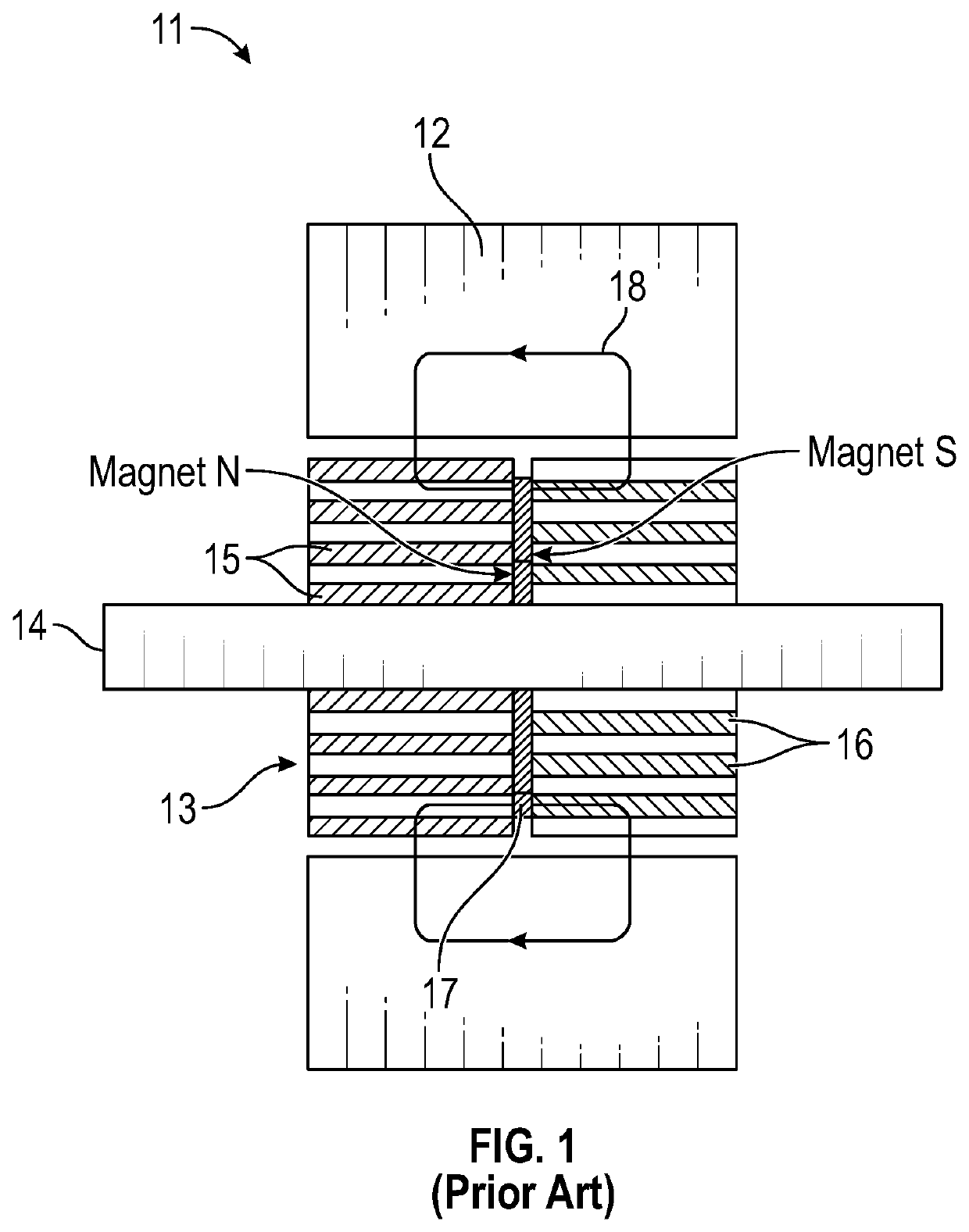
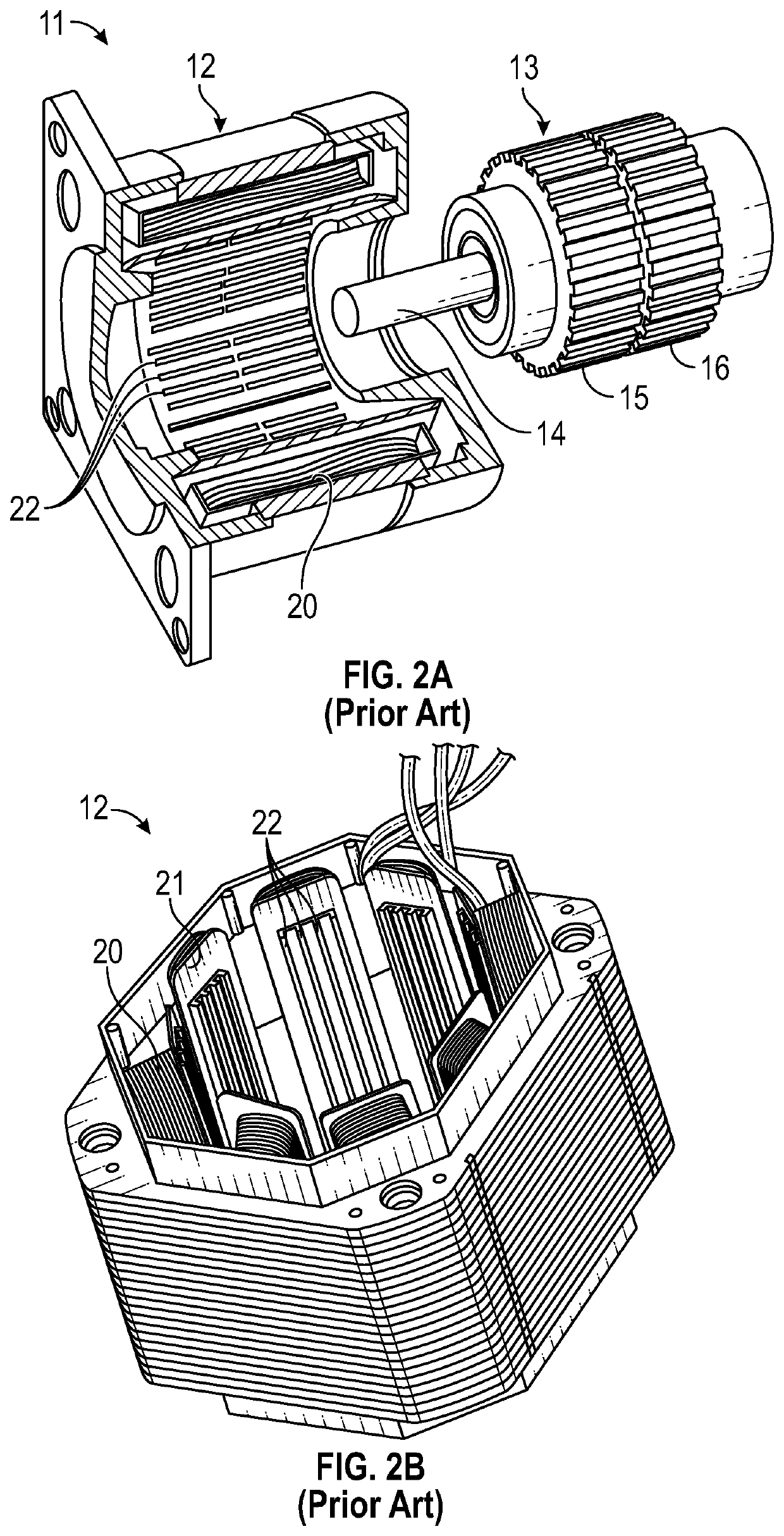
[0023]With reference to FIGS. 1, 2A and 2B, a conventional hybrid step motor 11 of the prior art is shown by way of comparison. This step motor includes a stator assembly 12 and a hybrid-type rotor 13. The rotor 13 is mounted on an axial shaft 14 that is supported for rotation within the stator assembly 12, e.g. via a pair of precision bearings.

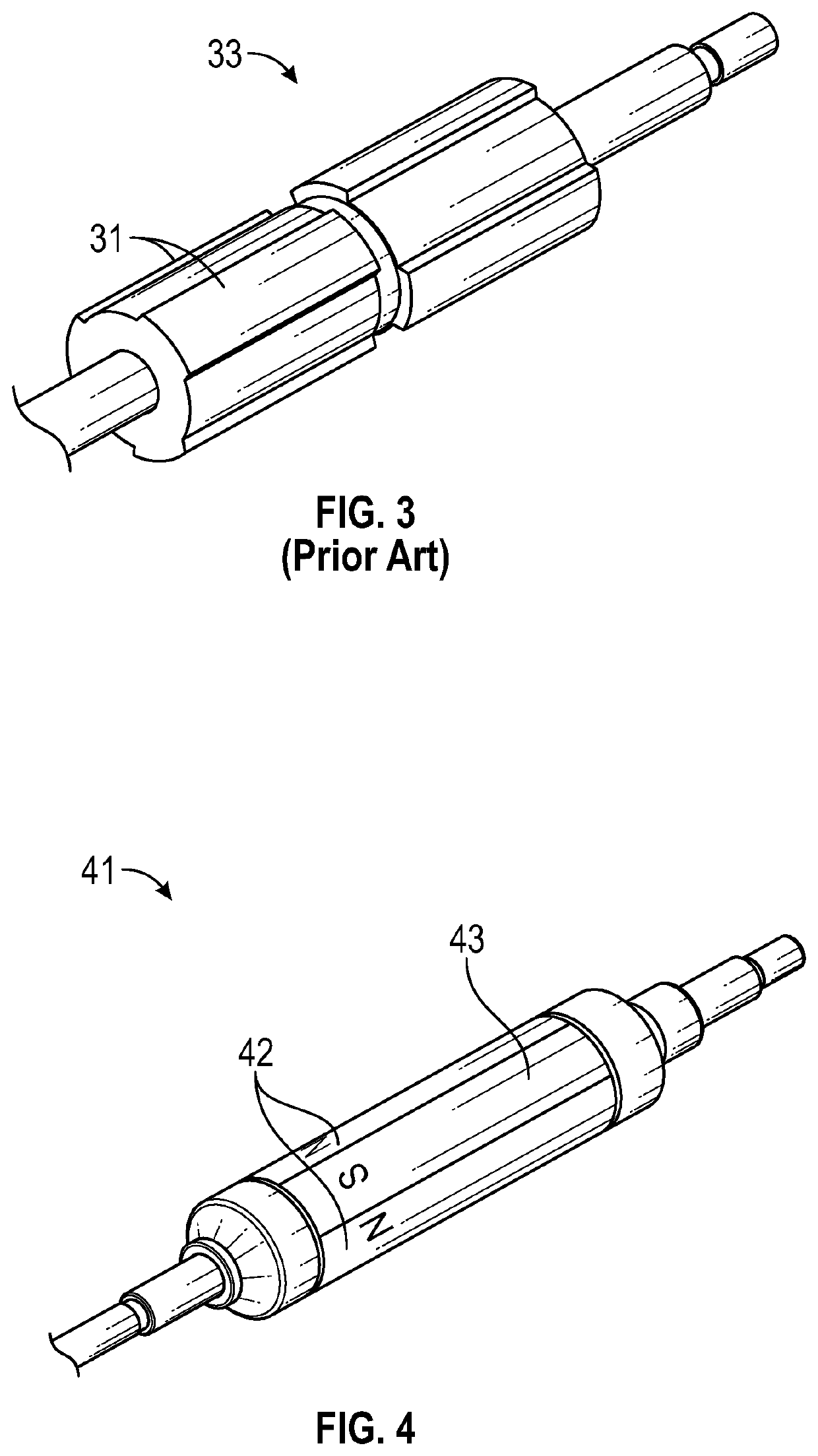
[0024]The hybrid-type rotor has two parts with respective rotor teeth 15 and 16 that sandwich a disc magnet 17. The teeth 15 in one of the rotor parts are circumferentially offset by one-half pitch relative to the teeth 16 in the other of the rotor parts, so that teeth 15 define magnetic N rotor poles and teeth 16 define magnetic S rotor poles. Another hybrid-type rotor with fewer rotor teeth 31 is shown in FIG. 3. This kind of hybrid rotor arrangement provides for a long three-dimensional magnetic flux path 18 through the motor 11, resulting in greater reluctance and winding induction, and slower current rise time between successive phases t...


PUM


Abstract

A two-phase stepper motor with a permanent magnet (PM) rotor and a modified hybrid-type stator is provided. The modified hybrid stator can be manufactured even at the smaller motor size because it employs shoeless, straight stator poles without stator teeth and with bobbin coils that are pre-wound outside the motor and easily inserted over each of the stator poles. Each bobbin may be an elongated continuous belt of insulative material with a hollow interior that forms a sleeve that fits around its corresponding stator pole. Conductive wire wound around the sleeve forms the stator coils. Edges of the sleeve may have exterior flanges at radially inner and outer ends of the stator pole to hold windings in place and keep the sleeve from bowing outward. This stator construction allows the motor to be miniaturized so that the PM rotors can be 13 mm diameter or less.

Description

TECHNICAL FIELD[0001]The present invention relates to step motors, that is, electric motor structures designed to rotate step by step between established electromagnetic detent positions, especially step motors having permanent magnet (PM) type rotors and hybrid stators, and in particular to any having design features that permit manufacture of ever smaller motors.BACKGROUND ART[0002]Demand for smaller motors is high for a number of applications, such as medical and laboratory equipment (e.g. centrifuges), pumps, fans, printers and copiers, material handling, as well as many positioning or speed control devices used in motion control. Low noise is also required in many of these applications, and so a major design goal is not only to reduce motor size but at the same time also to reduce motor noise and vibration. Most step motors, which are widely used where precise positioning is a requirement, are designed for low speed operation. But increasingly there is demand (e.g. in centrifug...

Claims


Application Information

Patent Timeline
Patent Type & Authority Applications(United States)
IPC IPC(8): H02K17/12H02K37/14H02K15/02
CPCH02K17/12H02K37/14H02K15/08H02K2213/03H02K15/02H02K1/278H02K15/03H02K19/10
Inventor LIN, TED T.LIU, JINPING
Owner LIN ENG INC
Why Eureka
Eureka Blog
Learn More