Eureka AIR delivers breakthrough ideas for toughest innovation challenges, trusted by R&D personnel around the world.

Biological battery and biological cathode

a biological battery and battery technology, applied in the field of biological batteries and biological cathodes, can solve the problems of lack of suitable catalysts, limited li-air cell performance, and high cost of metals, and achieve the effects of increasing production efficiency, reducing the cost of metals, and improving the efficiency of electrical current production

Active Publication Date: 2020-05-19
ZHANG PEI
View PDF9 Cites 1 Cited by
  • Summary
  • Abstract
  • Description
  • Claims
  • Application Information

AI Technical Summary

Benefits of technology

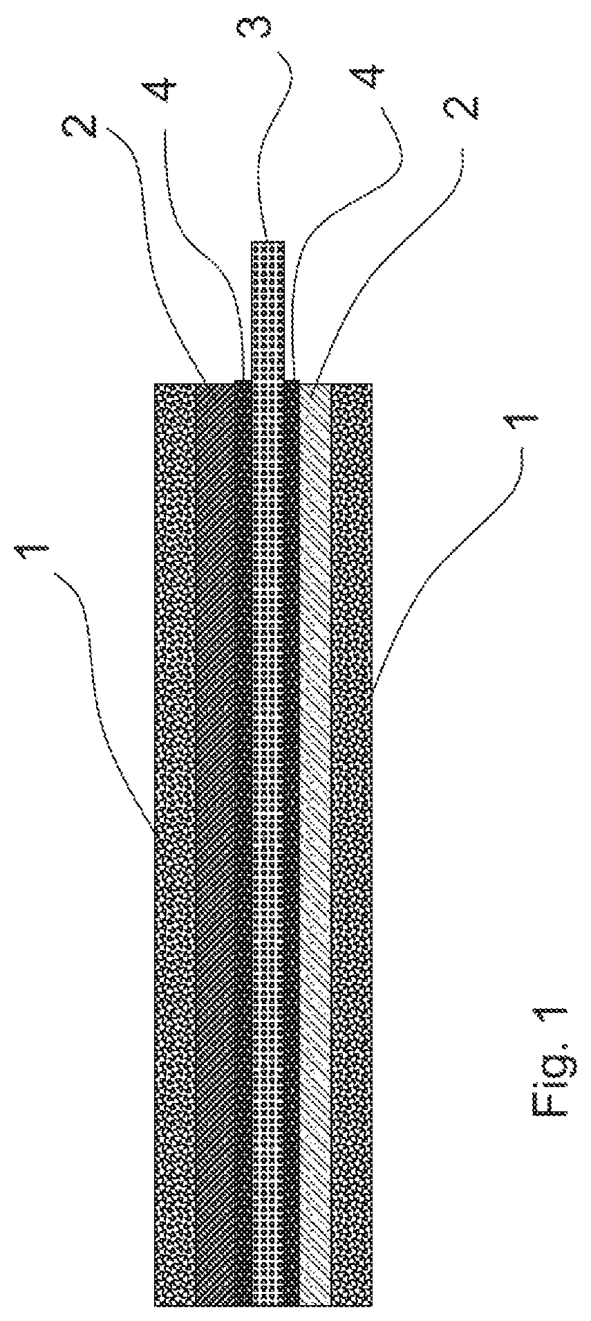
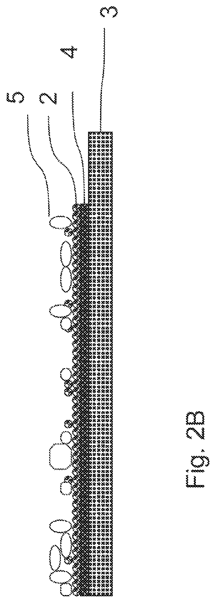
The invention provides a biological cathode composition and construction method, as well as a biological metal-air battery that can be used as a longer-lasting, safer and friendly battery. The biological cathode can convert carbon feedstock into organic chemicals at increased production efficiency. The invention also provides a method for improving the surface properties of the electrode to enhance the bacteria electrode surface coverage ratio to about 80%, which results in better performance without increasing the surface area of the cathode electrode. The hydrophobic treatment of the electrodes improves biocathode performance, allowing for faster production of electrical current. The invention also provides a method for optimizing pore size in carbon materials to enhance the bacteria electrode surface coverage ratio and improve current production.

Problems solved by technology

However the metals are expensive and less easy to access.
Li-air cell performance is limited by the efficiency of reaction at the cathode, where most of the cell voltage drop occurs (Kraytsberg 2010).
Part of the reason for the undeveloped potential of Li-air cells lays with the lack of a suitable catalyst for effecting the oxygen reduction.
As same as Lithium-air battery, the cathode oxidation reaction rate limits the performance of the zinc-air battery.
Treasure metal catalysts are costive and some are causing environmental issues.
Over the time, the metal oxide compounds are accumulated and clog the pore orifices causing termination of the Metal-air battery during discharge process.
As well, MFCs can be applied in occasions that battery or other power sources are not feasible, such as powering marine underwater devices etc.
However the reduction of oxygen is critical and usually the limiting step for power generation.
Chemical catalysts for the cathode, for example, plain Pt (Reimers, 2001) or Pt-coated carbon (Rozendal 2007) are expensive and only have limited life time (Schamphelaire 2008).
Applying noble metals such as platinum in the cathode represents a capital challenge, not only because the substantial increase of the capital costs but also because of the sensitivity of the catalysts to poisoning issues in WC working conditions.
However, the performance is limited because of the lack of high-efficiency, functional microorganisms, low microorganism surface interaction with electrode material, medium composition, and other factors.
In many cases, CO2 and other gases are discharged directly to the atmosphere, placing a heavy pollution burden on the environment.
However, the available techniques are mostly physical and chemical methods, which require tremendous levels of energy.
Producing acetic acid consumes fossil fuels, which are energy-intensive and costly (Seth 2010).
However, this synthetic process requires relatively high temperatures and pressures, exotic materials of construction, and extensive safety-related equipment.
The result is a high capital cost.
This biological route accounts for only about 10% of world production, owing to the high cost of consumption of food material, occupation of land, etc.
However, it requires strict anaerobic conditions, which demand high operation and maintenance cost.

Method used


Image

  • Biological battery and biological cathode
  • Biological battery and biological cathode
  • Biological battery and biological cathode

Examples


examples

[0075]FIG. 3 illustrates an acetic acid production system and process workflow according to at least one preferred embodiment of the invention. Referring to FIG. 3, at least one of air gas and / or a gas containing carbon dioxide is introduced via influent port 1 to an influent mixing tank 3. A medium solution feedstock influent port 2 also enables such feedstock to be added to the influent mixing tank 3. The influent mixing chamber is connected by piping or other means allowing fluid connection to a bioreactor 8. The preferable range of the volume of the reactor can be from 100 ml to 30 m3.

[0076]A more preferred range is between 100 ml and 1 m3. The bioreactor is preferably a batch reactor or chemostat preferably at a flow rate between 1 ml / min to 100 ml / min, and more preferably a flow rate between 1 ml / min and 10 ml / min. Permeable membrane 5 is disposed within the bioreactor 8 such that two sides are created within the bioreactor on either side of the membrane 5. The membrane can be...


PUM

PropertyMeasurementUnit
sizeaaaaaaaaaa
sizeaaaaaaaaaa
pore sizeaaaaaaaaaa

Abstract

Biological material is used to build up biological cathode electrodes (biological cathode) and biological batteries, particularly biological metal air batteries as well as biological flow battery. A biological battery system includes a reaction vessel, a medium, a conductive anode and a biological cathode electrode. The biological cathode has a conductive support layer, a polymeric binding layer disposed between the conductive support layer and a contact layer. The contact layer being configured to be in electrical contact with biological components in the medium or being deposited with biological components. When the reaction vessel is open to an ambient air, the biological components accept electrons from the cathode.

Description

FIELD OF THE INVENTION[0001]The invention concerns processes / methods of utilizing biological material to build up biological electrodes and biological / green batteries, particularly biological metal-air batteries as well as fuel cells. This invention also related to using biological material to produce useful anions, cations, acetic acid and other chemical compounds under certain electrochemical conditions.BACKGROUNDBatteries and Metal-Air Batteries[0002]A battery is a device consisting of one or more electrochemical cells convert stored chemical energy into electrical energy. Each cell contains a positive terminal, or cathode, and a negative terminal, or anode. Electrolytes allow ions to move between the electrodes and terminals to generate current, which flows out of the battery to perform work. According to a 2005 estimate, the worldwide battery industry generates US$48 billion in sales each year, with 6% annual growth. A metal-air battery is an electrochemical cell that uses an a...

Claims


Application Information

Patent Timeline
Patent Type & Authority Patents(United States)
IPC IPC(8): H01M8/16C12M1/00C12M1/42H01M12/08H01M4/90H01M4/86
CPCC12M35/02H01M8/16H01M4/9075C12M43/08H01M4/9008H01M12/08H01M2004/8689H01M4/8668H01M4/8673H01M4/90Y02E60/50
Inventor ZHANG, PEI
Owner ZHANG PEI
Why Eureka
Eureka Blog
Learn More