Injector piston with improved seal

a technology of injector pistons and seals, applied in the field of seals, can solve problems such as seal failure and piston malfunction

Pending Publication Date: 2022-03-10
LINCOLN INDUSTRIES CORP +1
View PDF4 Cites 0 Cited by
  • Summary
  • Abstract
  • Description
  • Claims
  • Application Information

AI Technical Summary

Benefits of technology

The piston assembly described in the patent text has several advantages over older designs. Firstly, the piston body is easier to make and the seal is easier to install. Secondly, the seal with its deflectable lip avoids issues with concentricity and tolerance stack-ups. Lastly, the seal instead of the piston engaging with the chamber end face eliminates the need for a high-quality surface finish on the piston.

Problems solved by technology

Depending on the seal design, fluid pressure may cause portions of the seal material to become extruded between the head and the chamber wall, leading to seal failure and malfunctioning of the piston.

Method used


Image

  • Injector piston with improved seal
  • Injector piston with improved seal
  • Injector piston with improved seal

Examples


Embodiment Construction

[0019]Certain terminology is used in the following description for convenience only and is not limiting. The words “inner”, “inwardly” and “outer”, “outwardly” refer to directions toward and away from, respectively, a designated centerline or a geometric center of an element being described, the particular meaning being readily apparent from the context of the description. Further, as used herein, the words “connected” and “coupled” are each intended to include direct connections between two members without any other members interposed therebetween and indirect connections between members in which one or more other members are interposed therebetween. The terminology includes the words specifically mentioned above, derivatives thereof, and words of similar import.

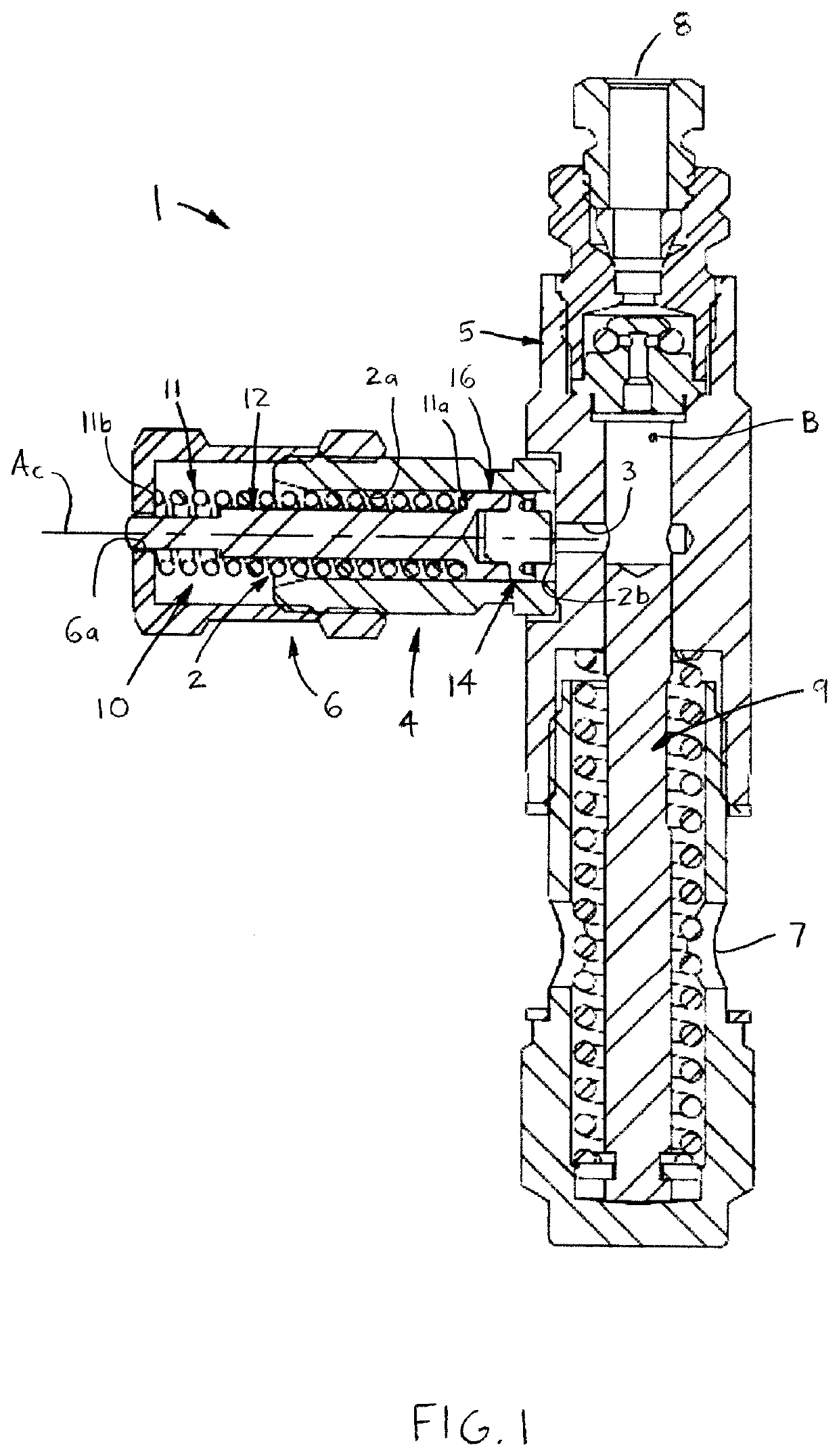
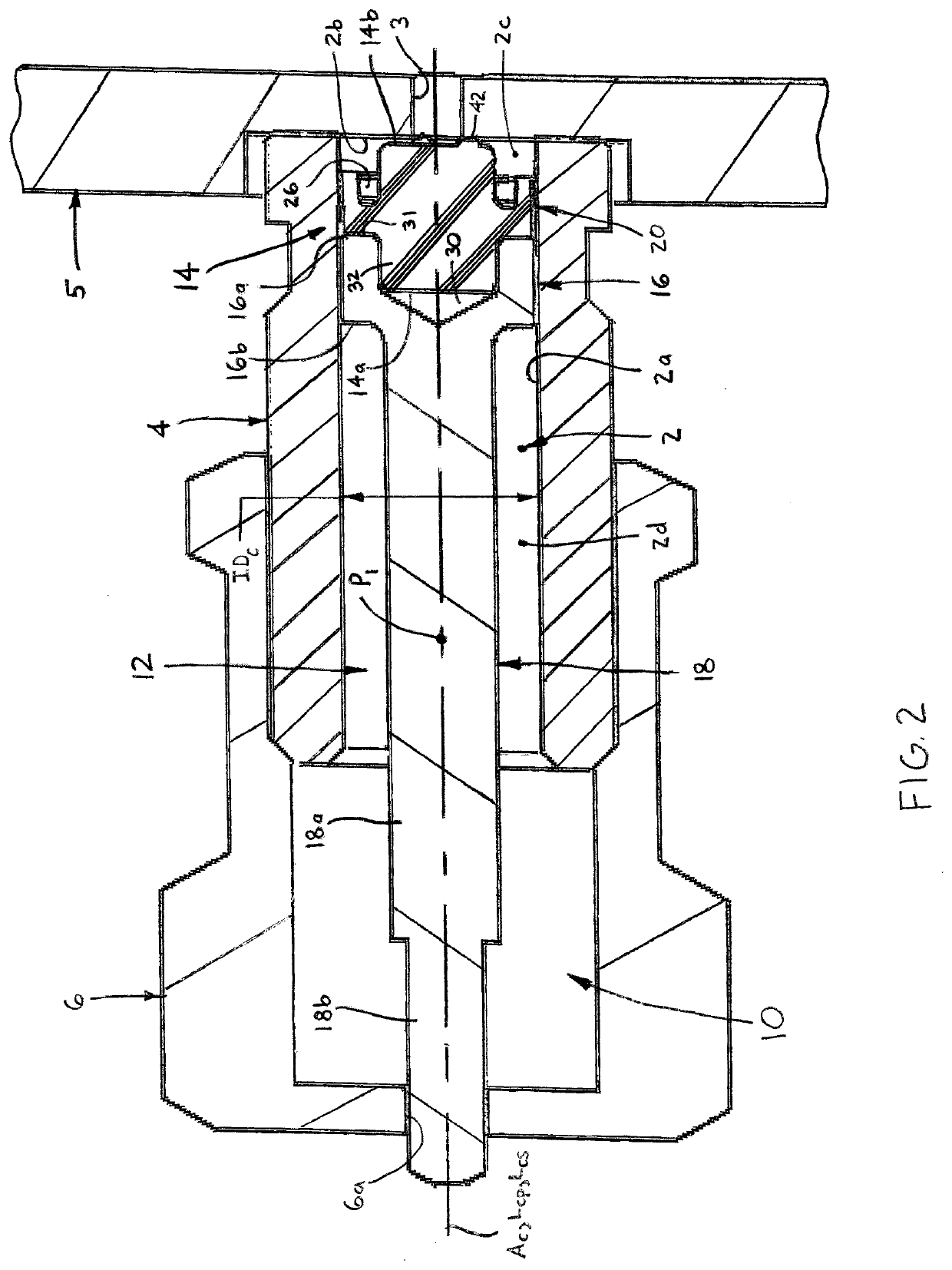
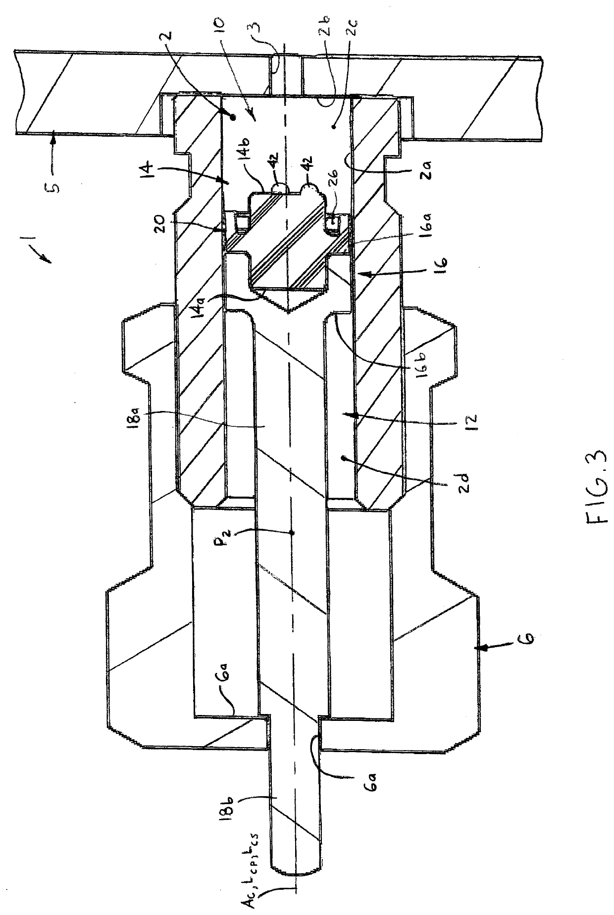
[0020]Referring now to the drawings in detail, wherein like numbers are used to indicate like elements throughout, there is shown in FIGS. 1-12 a dosing piston assembly 10 for a fluid delivery device 1, preferably a lubrica...


PUM


Abstract

A piston assembly is for a fluid delivery device, preferably a lubricant injector, the injector having a measuring chamber defined by an inner cylindrical surface and an axial end face, a flow port through the end face, and a central axis extending through the chamber. The piston assembly includes a piston body disposeable within the chamber so as to be linearly displaceable along the central axis. The piston body includes a cylindrical head, the head having first and second axial ends and an outer circumferential surface, and a rod extending axially from the second axial end of the piston head. A seal is coupled with the first axial end of the piston head and has an annular lip sealingly engageable with the chamber inner cylindrical surface and an axial end engageable with the chamber end face.

Description

BACKGROUND OF THE INVENTION[0001]The present invention relates to seals, and more particularly to seals for injector pistons.[0002]Lubricant injectors typically include a measuring chamber to meter a desired quantity of lubricant for subsequent injection to a specific point to be lubricated, such as a bearing, a gear face, etc. A piston is disposed within the chamber and displaces away from a port as lubricant enters the chamber until reaching a stop, at which point the chamber is filed with the desired quantity. Thereafter, the lubricant is ejected from the chamber through the port by a subsequent return stroke of the piston.[0003]A typical lubricant piston includes a head sized slightly lesser than the measuring chamber bore and a rod extending from a rear end of the head, which functions to both guide the head and provides as an external visual indicator. During both the filling and ejecting of lubricant, the piston head must be sealed to prevent leakage about the head, which can...

Claims


Application Information

Patent Timeline
Patent Type & Authority Applications(United States)
IPC IPC(8): F16N25/02F16N27/00F16J9/12
CPCF16N25/02F16J9/12F16N27/00F04B53/14F04B53/143F04B13/00F04B53/16F16N13/02F16J1/008
Inventor MCBRIDE, TADDHOLLAND, CHRISGREEN, BRANDON
Owner LINCOLN INDUSTRIES CORP
Why Eureka
Try Eureka