Flow measurement for a gas turbine engine

a gas turbine engine and flow measurement technology, applied in the direction of machines/engines, heat measurement, instruments, etc., can solve the problems of inability to accurately calculate the bulk airflow, model robustness, and limited region samples, so as to achieve the effect of reducing rotational speed and varying the rotational speed of the fan

Pending Publication Date: 2022-03-10
VIRGINIA TECH INTPROP INC
View PDF5 Cites 1 Cited by
  • Summary
  • Abstract
  • Description
  • Claims
  • Application Information

AI Technical Summary

Benefits of technology

[0029]Each fan blade may be defined as having a radial span extending from a root (or hub) at a radially inner gas-washed location, or 0% span position, to a tip at a 100% span position. The ratio of the radius of the fan blade at the hub to the radius of the fan blade at the tip may be less than (or on the order of) any of: 0.4, 0.39, 0.38 0.37, 0.36, 0.35, 0.34, 0.33, 0.32, 0.31, 0.3, 0.29, 0.28, 0.27, 0.26, or 0.25. The ratio of the radius of the fan blade at the hub to the radius of the fan blade at the tip may be in an inclusive range bounded by any two of the values in the previous sentence (i.e. the values may form upper or lower bounds), for example in the range of from 0.28 to 0.32. These ratios may commonly be referred to as the hub-to-tip ratio. The radius at the hub and the radius at the tip may both be measured at the leading edge (or axially forwardmost) part of the blade. The hub-to-tip ratio refers, of course, to the gas-washed portion of the fan blade, i.e. the portion radially outside any platform.
[0030]The radius of the fan may be measured between the engine centreline and the tip of a fan blade at its leading edge. The fan diameter (which may simply be twice the radius of the fan) may be greater than (or on the order of) any of: 220 cm, 230 cm, 240 cm, 250 cm (around 100 inches), 260 cm, 270 cm (around 105 inches), 280 cm (around 110 inches), 290 cm (around 115 inches), 300 cm (around 120 inches), 310 cm, 320 cm (around 125 inches), 330 cm (around 130 inches), 340 cm (around 135 inches), 350 cm, 360 cm (around 140 inches), 370 cm (around 145 inches), 380 (around 150 inches) cm, 390 cm (around 155 inches), 400 cm, 410 cm (around 160 inches) or 420 cm (around 165 inches). The fan diameter may be in an inclusive range bounded by any two of the values in the previous sentence (i.e. the values may form upper or lower bounds), for example in the range of from 240 cm to 280 cm or 330 cm to 380 cm.
[0031]The rotational speed of the fan may vary in use. Generally, the rotational speed is lower for fans with a higher diameter. Purely by way of non-limitative example, the rotational speed of the fan at cruise conditions may be less than 2500 rpm, for example less than 2300 rpm. Purely by way of further non-limitative example, the rotational speed of the fan at cruise conditions for an engine having a fan diameter in the range of from 220 cm to 300 cm (for example 240 cm to 280 cm or 250 cm to 270 cm) may be in the range of from 1700 rpm to 2500 rpm, for example in the range of from 1800 rpm to 2300 rpm, for example in the range of from 1900 rpm to 2100 rpm. Purely by way of further non-limitative example, the rotational speed of the fan at cruise conditions for an engine having a fan diameter in the range of from 330 cm to 380 cm may be in the range of from 1200 rpm to 2000 rpm, for example in the range of from 1300 rpm to 1800 rpm, for example in the range of from 1400 rpm to 1800 rpm.

Problems solved by technology

Furthermore, the samples in the limited region may not be representative of the bulk airflow, for example, it may be influenced by the boundary layer of the airflow along the casing.
Therefore, the correlation model may not be robust to a changing operating condition and so the calculation of the bulk airflow may not be accurate.
Another problem faced when attempting to measure flow rates on axial flow machines such as gas turbine engines is that compressibility effects of the flow become relevant for high volumetric flow rates.
This complicates models that might need to be used to correlate sensor readings to overall / bulk flow rate values.

Method used


Image

  • Flow measurement for a gas turbine engine
  • Flow measurement for a gas turbine engine
  • Flow measurement for a gas turbine engine

Examples


Embodiment Construction

[0063]Embodiments will now be described by way of example only, with reference to the Figures.

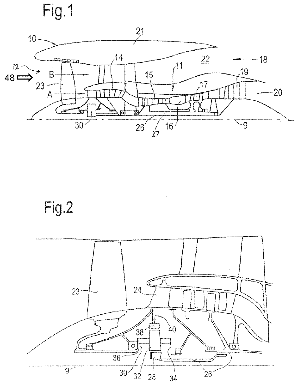
[0064]FIG. 1 illustrates a gas turbine engine 10 having a principal rotational axis 9. The engine 10 comprises an air intake 12 which receives an intake airflow 48 and a propulsive fan 23 that generates two airflows: a core airflow A and a bypass airflow B. The intake airflow 48 comprises the sum total of the air flowing into the operational upstream end of the engine 10, with the sum total of the core airflow A and the bypass airflow B substantially equal to the intake airflow 48.

[0065]The gas turbine engine 10 comprises a core 11 that receives the core airflow A. The engine core 11 comprises, in axial flow series, a low pressure compressor 14, a high-pressure compressor 15, combustion equipment 16, a high-pressure turbine 17, a low pressure turbine 19 and a core exhaust nozzle 20. A nacelle 21 surrounds the gas turbine engine 10 and defines a bypass duct 22 and a bypass exhaust nozzle 18....


PUM

PropertyMeasurementUnit
diameteraaaaaaaaaa
diameteraaaaaaaaaa
diameteraaaaaaaaaa

Abstract

A method of thermodynamic assessment of flow through a turbomachine having a compressor, comprising: receiving sensor readings from a plurality of acoustic sensors located about an intake for the turbomachine upstream of the compressor; and receiving pressure and stagnation temperature readings for the flow into the intake. A static temperature is determined for the flow into the intake and an average velocity of the flow over a flow area of the intake upstream of the compressor using the acoustic sensor readings. A mass flow rate of the flow through the intake is determined using the average velocity of the flow and the stagnation pressure.

Description

BACKGROUNDField of the Disclosure[0001]The present disclosure relates to an acoustic measurement system, particularly to an acoustic measurement system for a turbomachine, such as an axial flow engine.Description of the Related Art[0002]In turbomachines, for example gas turbine engines, measurement of the properties of the air flowing into or through the engine can be used to determine the performance of the engine. For example, the average flow velocity or the mass flow of the airflow can be used to calculate the performance and / or efficiency of the engine.[0003]Measurements of total and static pressure may be performed using conventional devices, such as Pitot tubes. Pitot tubes comprise an aperture configured to face into the oncoming airflow and must protrude / extend into the airflow, for example, to avoid a boundary airflow layer in an inner surface of the casing / ducting surrounding the airflow. Other devices, such as static ports must be mounted within the casing.[0004]The exte...

Claims


Application Information

Patent Timeline
Patent Type & Authority Applications(United States)
IPC IPC(8): G01F1/66G01K11/24G01M15/14
CPCG01F1/667G01M15/14G01K11/24F01D21/003F01D25/00F02C9/00F01D17/08F05D2210/30F05D2260/80F05D2270/3061F05D2270/80F05D2270/806Y02T50/60
Inventor KYRITSIS, VASILEIOSLOWE, KEVIN TODDBRISTOW, MAURICELOFTUS, PETER
Owner VIRGINIA TECH INTPROP INC
Why Eureka
Try Eureka