Injection system for turbomachine, comprising a swirler and mixing bowl vortex holes

a technology of injection system and turbomachine, which is applied in the direction of combustion process, lighting and heating apparatus, climate sustainability, etc., can solve the problems of limited injection system mass and reduced size, and achieve the effect of reducing size, easy manufacturing and convenient manufactur

Active Publication Date: 2022-03-17
SN DETUDE & DE CONSTR DE MOTEURS DAVIATION S N E C M A
View PDF0 Cites 1 Cited by
  • Summary
  • Abstract
  • Description
  • Claims
  • Application Information

AI Technical Summary

Benefits of technology

[0009]Thanks to the vortex holes, the injection system can comprise a sole swirler. The structure of the mixing bowl can also remove the need for a venturi which is conventionally situated between a swirler and the mixing bowl. This may result in a reduced size and a limitation of the mass of the injection system, while allowing satisfactory spraying of the air-fuel mixture into the combustion chamber. Furthermore, the injection system tends to be easier to manufacture.
[0010]In particular, the atomisation of the air-fuel mixture into the combustion chamber is satisfactory. There are no more problems with flow of the air-fuel mixture in a venturi which has been eliminated.
[0011]Due to the presence of a sole swirler and the absence of a venturi, the injection system is easier to manufacture. The single swirler of the injection system has a larger diameter around the longitudinal axis of the injection system, and the diameter of the holes in the mixing bowl forming the vortex holes is increased, which further facilitates the manufacture of the injection system.
[0012]The presence of a sole swirler and the absence of a venturi tends to reduce the mass and size of the injection system.

Problems solved by technology

This may result in a reduced size and a limitation of the mass of the injection system, while allowing satisfactory spraying of the air-fuel mixture into the combustion chamber.

Method used


Image

  • Injection system for turbomachine, comprising a swirler and mixing bowl vortex holes
  • Injection system for turbomachine, comprising a swirler and mixing bowl vortex holes
  • Injection system for turbomachine, comprising a swirler and mixing bowl vortex holes

Examples


Embodiment Construction

[0034]Identical, similar or equivalent parts of the various figures are given the same reference numbers in order to facilitate the passage from one figure to another.

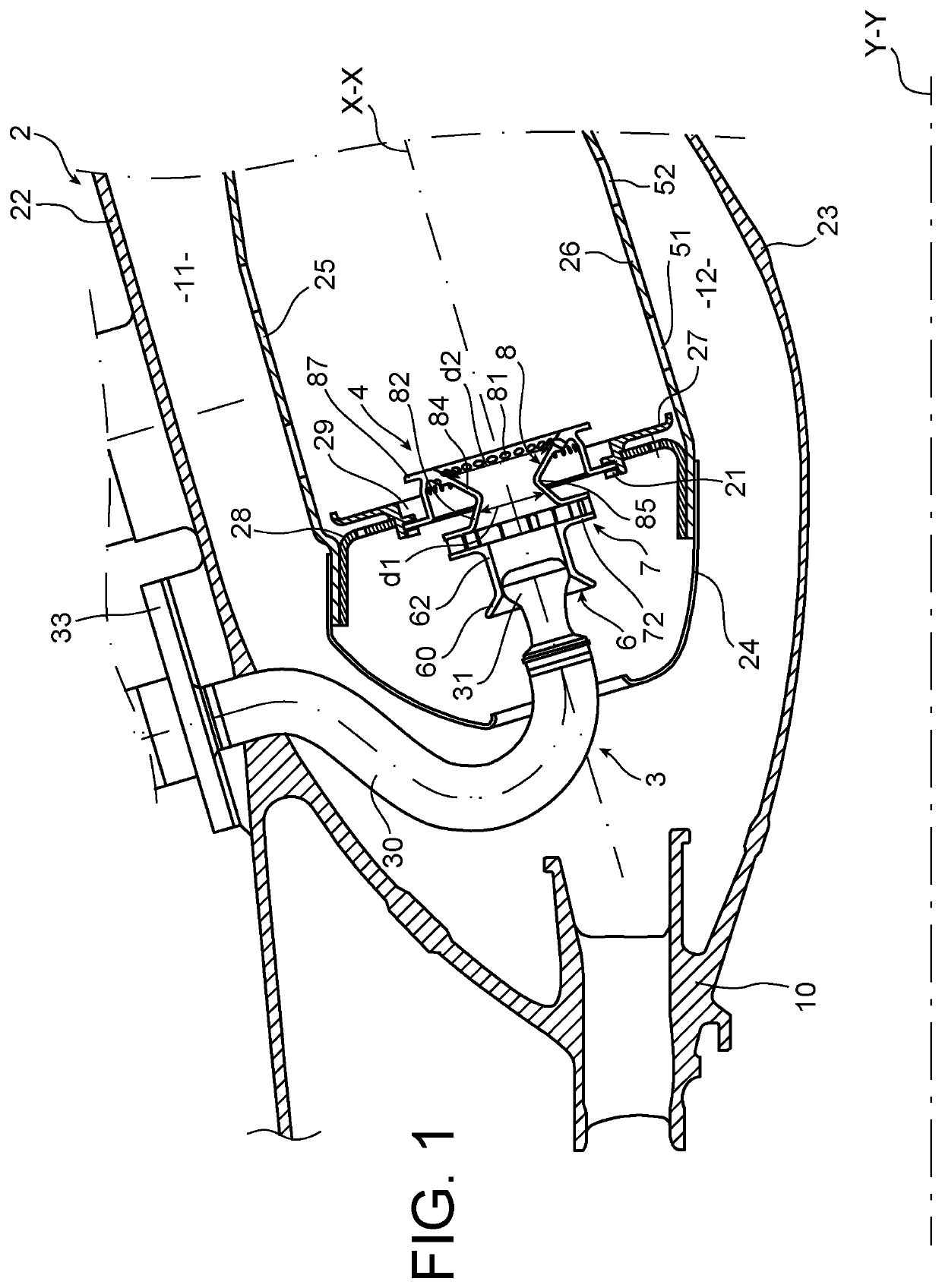
[0035]FIG. 1 represents, in schematic manner, a combustion chamber 2 of an aircraft turbomachine. The combustion chamber 2 is annular around a longitudinal axis Y-Y of the turbomachine.

[0036]It has an outer casing wall 22 and an inner casing wall 23, a fairing 24, an outer wall 25 and an inner wall 26 which are joined by a chamber bottom 28.

[0037]It also comprises injectors 3, injection systems 4 and a diffuser 10 and upstream retention members 21 of the injection systems 4.

[0038]The outer casing wall 22 delimits the combustion chamber 2 radially outwards with respect to the longitudinal axis Y-Y of the turbomachine. The inner casing wall 23 is radially located towards the inside with respect to the outer wall 22 relative to the longitudinal axis Y-Y of the turbomachine.

[0039]The outer casing wall 22 delimits, with the...


PUM


Abstract

An injection system for a turbomachine combustion chamber includes a swirler and a mixing bowl. The mixing bowl includes a converging frustoconical portion and a diverging frustoconical portion. The diverging frustoconical portion is connected to the converging frustoconical portion, forming a continuous aerodynamic profile with the converging frustoconical portion. The diverging frustoconical portion is passed through by vortex holes which each includes a circumferential component around a longitudinal axis of the injection system and an axial component along the longitudinal axis of the injection system.

Description

TECHNICAL FIELD[0001]The invention relates to the general technical field of aircraft turbomachines, such as turbojet engines and turbopropellers. It relates to an injection system for a turbomachine combustion chamber.Background of the Invention[0002]A turbomachine annular combustion chamber generally comprises a plurality of injection systems which are inserted in openings in a bottom of the combustion chamber. A fuel injector is housed in each of the injection systems.[0003]Snecma patent application FR 2 903 169 relates to an injection system which comprises an internal swirler, a venturi and a mixing bowl. The mixing bowl comprises vortex holes. These mixing bowl vortex holes are located radially outside the venturi and around the venturi. They are located in an upstream portion of the mixing bowl, which is cylindrical with circular cross-section.[0004]The size of the injection system of application FR 2 903 169 is limited, while allowing relatively satisfactory spraying of the ...

Claims


Application Information

Patent Timeline
Patent Type & Authority Applications(United States)
IPC IPC(8): F23R3/14F23R3/28
CPCF23R3/14F23R3/286F23R3/283F23R3/12F23R2900/03044Y02T50/60
Inventor BOURGOIS, SÉBASTIEN ALAIN CHRISTOPHELUNEL, ROMAIN NICOLASMUSAEFENDIC, HARIS
Owner SN DETUDE & DE CONSTR DE MOTEURS DAVIATION S N E C M A
Why Eureka
Try Eureka