Wire-grid polarizer and process for producing the same

a polarizer and wire-grid technology, applied in the field of wire-grid polarizers, can solve the problems of difficult stably manufacturing a low-reflection wire-grid polarizer, difficult to manufacture polarizers, etc., and achieve the effects of reducing the reflectance of incident light, excellent polarization performance, and maintaining the required light transmittan

Pending Publication Date: 2022-03-17
NAT INST OF ADVANCED IND SCI & TECH +1
View PDF0 Cites 0 Cited by
  • Summary
  • Abstract
  • Description
  • Claims
  • Application Information

AI Technical Summary

Benefits of technology

[0040]The wire-grid polarizer of the present invention has excellent polarization performance, can maintain required light transmittance and can significantly reduce the reflectance of incident light from the back side. Since each metal reflector (B) is embedded in each groove (C) of the sheet (A), the wire-grid polarizer of the present invention is scratch-resistant and has such high surface durability that the polarization function thereof is hardly affected even when it is rubbed or wiped.
[0041]In addition, since each metal reflector (B) is covered by each groove structure of the sheet (A), the number of exposed parts from the front surface can be reduced with the result that the oxidation of each metal reflector (B) hardly progresses, thereby making it possible to provide a wire-grid polarizer which has heat and humidity resistance and can maintain its performance for a long time even in outdoor or high-temperature and high-humidity environments.
[0042]Since the wire-grid polarizer of the present invention can be adapted to molding processes such as film insert molding and cast molding, molded products with low reflection and polarization function can also be realized. By selecting a thermoplastic resin to be used for the sheet (A), it is easy to obtain the wire-grid polarizer that is resistant to stretching, rigid, and bendable. Furthermore, the wire-grid polarizer of the present invention can be manufactured by printing and sintering techniques using ink containing metal fine particles or plating means and can be produced at relatively low cost because it does not require complicated and expensive equipment.

Problems solved by technology

However, with this technology, it is not easy to manufacture polarizers with large areas because of the need for high-precision film thickness control, and it is also not easy to stably manufacture a low-reflection wire-grid polarizer because of the complexity of the manufacturing process.

Method used


Image

  • Wire-grid polarizer and process for producing the same
  • Wire-grid polarizer and process for producing the same
  • Wire-grid polarizer and process for producing the same

Examples


example 1

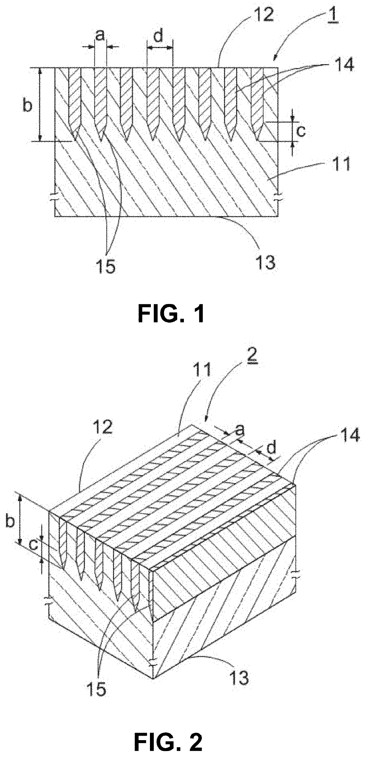
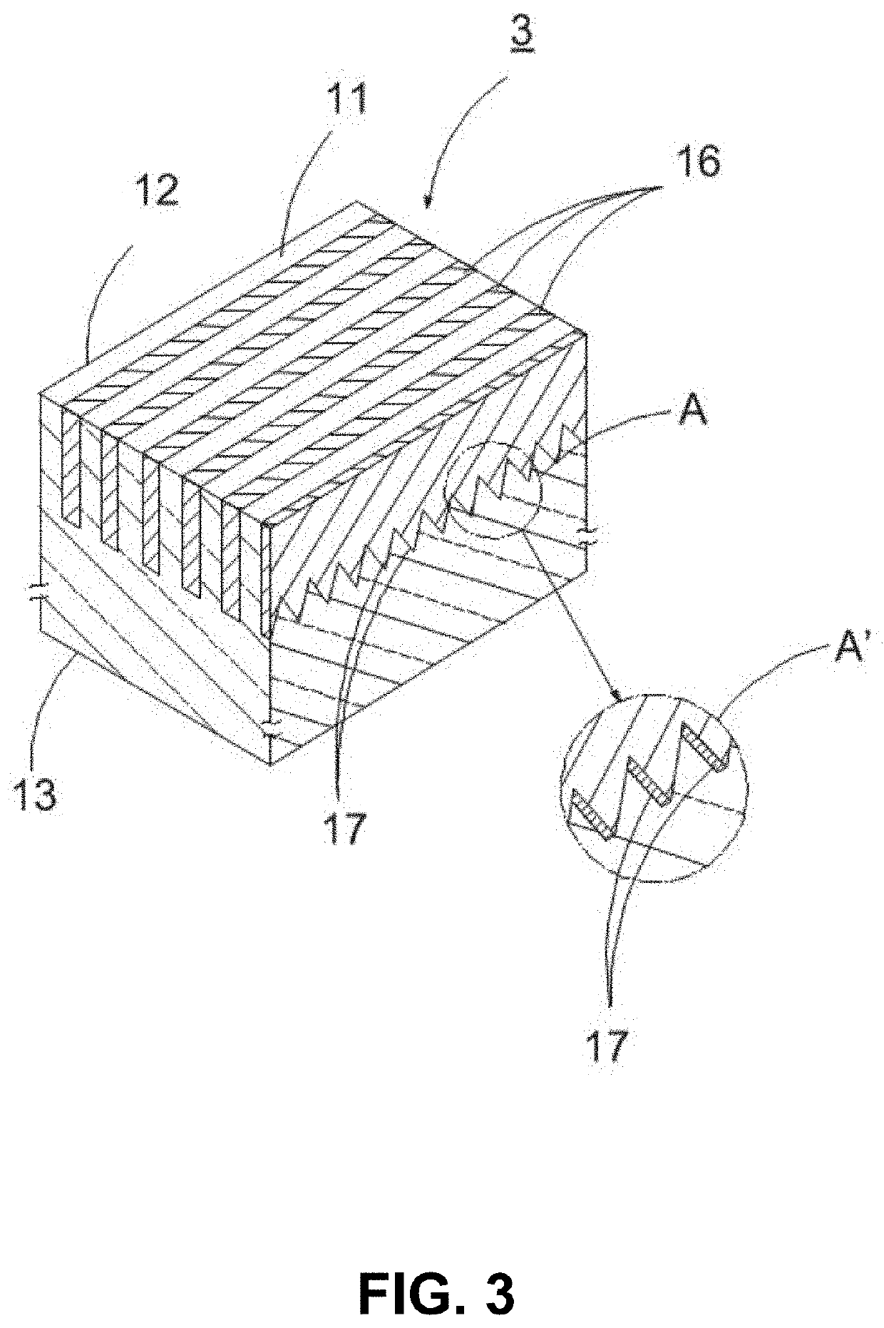
[0144]A microgroove structure was formed in the surface of a thermoplastic resin sheet by the thermal nanoimprinting method using a mold, followed by filling the grooves with ink containing silver microparticles, and then sintering the silver microparticles contained in the ink in a heated oven to prepare a polarizer specimen of the same type as the wire-grid polarizer (R1) described above.

[0145]The obtained polarizer specimen had an irregularly continuous concavo-convex shape at the tips in the one-dimensional grid array direction and in a cross-section perpendicular to the surface of the sheet.

(1) Formation of Microgroove Structure in Sheet Surface

[0146]A polycarbonate sheet (manufactured by Mitsubishi Engineering-Plastics Corporation, product name: FE-2000, thickness: 400 μm) was used as the transparent sheet. A mold used was made by microfabricating a 4-inch silicon wafer. As shown in Table 1 and notes thereof, the microstructure of the mold used had a convex shape for forming t...

examples 2 and 3

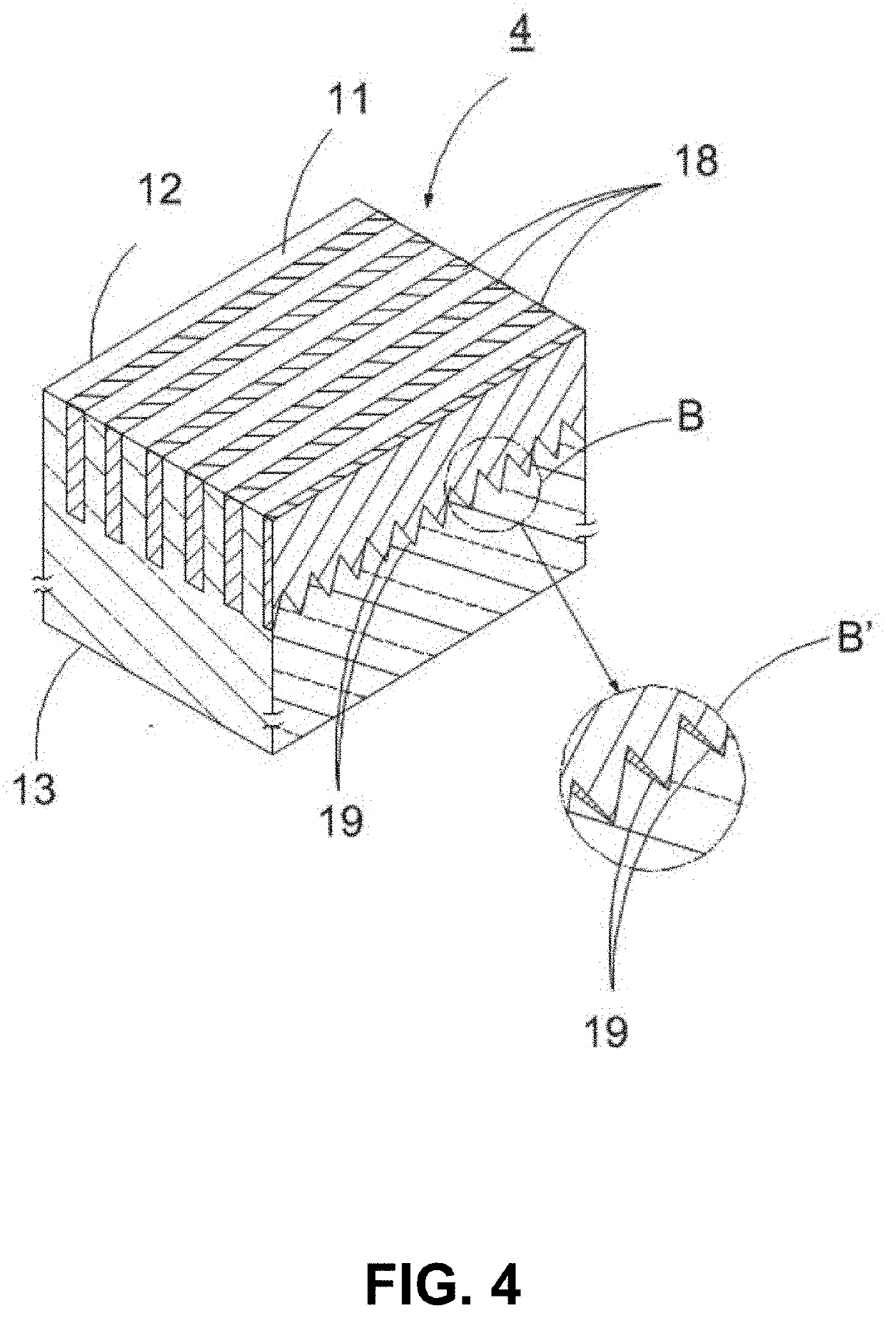
[0153]In Examples 2 and 3, microgroove structures were formed in the surfaces of the sheets using molds in the same manner as in Example 1, and, after ink was filled into the grooves, they were sintered to produce polarizer specimens which were of the same type as the wire-grid polarizer (R1) and had an irregularly continuous concavo-convex shape at the tips in a cross-section perpendicular to the sheet surface and in the one-dimensional grid array direction as in Example 1.

(1) Preparation of the Polarizer Specimens

[0154]The same transparent sheets as that used in Example 1 were used. As shown in Table 1 and notes thereof, the microstructures of the molds used were such that the shape of each of the convex parts for forming the grooves was the same as that of the above wire-grid polarizer (R1), the average width (a′) of the convex parts was 42.1 nm in Example 2 and 30.7 nm in Example 3, and the period (d′) of the array was 140 nm in Examples 2 and 3.

[0155]The average length (b′) up ...

examples 4 , 5 and 6

Examples 4, 5 and 6

[0161]Microgroove structures were formed in the surfaces of thermoplastic resin sheets by the thermal nanoimprinting method using molds, and then ink containing silver microparticles was filled into the grooves, followed by sintering of the silver microparticles contained in the ink in a heated oven to prepare polarizer specimens which were of the same type as the wire-grid polarizer (R1) and had an almost linear shape at the tips in a cross-section perpendicular to the surface of the sheet and in the one-dimensional grid array direction.

(1) Preparation of Polarizer Specimens

[0162]The same sheets as used in Example 1 were used. The microstructures of the molds used were such that the shape of each of convex parts forming the grooves was an inverted shape of the groove formed in the above wire-grid polarizer (R1), and the average width (a′), average length (b′), the average length (c′) toward the tip of the portions that gradually become thinner toward the tip and ...


PUM

PropertyMeasurementUnit
widthaaaaaaaaaa
reflectanceaaaaaaaaaa

Abstract

A wire-grid polarizer includes metal reflectors which are embedded in a large number of grooves formed in a one-dimensional grid pattern in the same direction and with the same period in the front surface of a transparent sheet, wherein the average width (a) of the metal reflectors is 200 nm or less, the ratio (b/a) of the average thickness (b) of the metal reflectors from the front side of the sheet to the tip in the backward direction to the above average width (a) is 4 to 25, in any cross-section perpendicular to the surface of the sheet, the shape of each of the metal reflectors in the vicinity of the tip in the thickness direction is such that it gradually becomes thinner in a linear or smoothly curved shape toward the tip, and the ratio of the average length (c) toward the tip of portions that gradually become thinner toward the tip to the above average width (a) is 1.2 or more.

Description

CROSS-REFERENCE TO RELATED APPLICATIONS[0001]This is a continuation application of a prior PCT application No. PCT / JP2020 / 019185 filed on May 14, 2020.TECHNICAL FIELD AND BACKGROUND ART[0002]The present invention relates to a wire-grid polarizer which is excellent in polarization performance, can maintain required light transmittance, has low reflectance on the back side and can be expected to be applied not only to optical products such as various displays, cameras, and optical measuring instruments, but also to polarized sunglasses and smart windows.[0003]Birefringent crystal, dichroic dye and wire-grid polarizers are known as the main polarizers in the optical field. Although the birefringent crystal polarizers are used for optical communications as devices having different output directions due to light incident on the optical axis of a birefringent crystal at an angle, their applications are limited because the crystal is used as a polarizer. The dichroic dye polarizers are wid...

Claims


Application Information

Patent Timeline
Patent Type & Authority Applications(United States)
IPC IPC(8): G02B5/30
CPCG02B5/3058G02B5/3041
Inventor HOKARI, RYOHEIKURIHARA, KAZUMATAKAKUWA, KYOHEIYAMAMOTO, AKITAKAYAMAGUCHI, YUSUKE
Owner NAT INST OF ADVANCED IND SCI & TECH
Why Eureka
Try Eureka