Information processing apparatus and control method
- Summary
- Abstract
- Description
- Claims
- Application Information
AI Technical Summary
Benefits of technology
Problems solved by technology
Method used
Image

Examples
first embodiment
[0036]First, an outline of an information processing apparatus according to a first embodiment will be described.
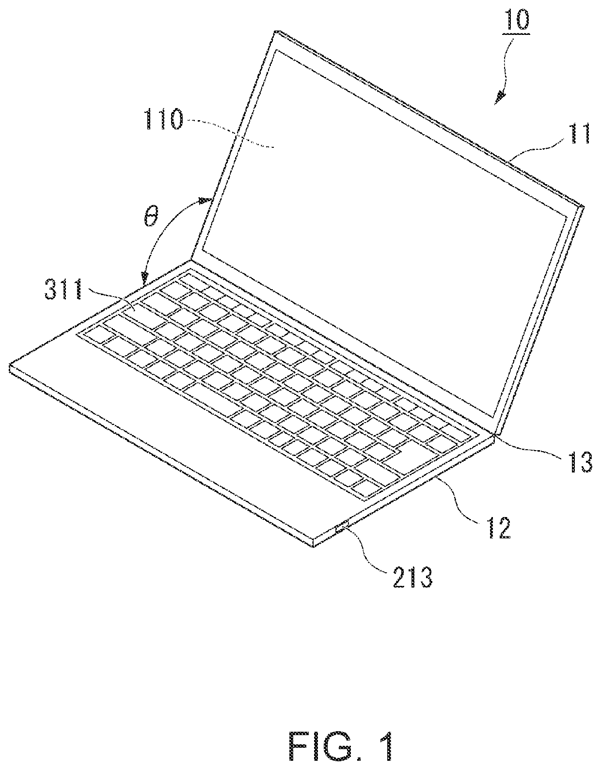
[0037]FIG. 1 is a perspective view illustrating the appearance of an information processing apparatus according to the present embodiment. An illustrated information processing apparatus is a clamshell laptop PC (Personal Computer). The information processing apparatus 10 includes a first chassis 11, a second chassis 12, and a hinge mechanism 13. The first chassis 11 and the second chassis 12 are substantially rectangular plate-shaped (for example, flat plate-shaped) chassis. One of the side faces of the first chassis 11 and one of the side faces of the second chassis 12 are combined (coupled) through the hinge mechanism 13 in such a manner that the first chassis 11 and the second chassis 12 relatively rotatable around an axis of rotation defined by the hinge mechanism 13. A state in which an open angle θ between the first chassis 11 and the second chassis 12 around the a...
second embodiment
[0096]In the first embodiment, the example in which the information processing apparatus 10 turns off the VBUS (to stop the power supply to the USB connector 213) when detecting that the first chassis 11 and the second chassis 12 are in the closed state and detecting the signal indicating that the PCH 200 has entered the sleep state is described, but the VBUS may also be turned off (to stop the power supply to the USB connector 213) regardless of whether the first chassis 11 and the second chassis 12 are in the closed state or not. In a second embodiment, an example in which the VBUS is turned off (to stop the power supply to the USB connector 213) when the signal indicating that the PCH 200 has entered the sleep state will be described.
[0097]FIG. 8 is a flowchart illustrating an example of VBUS off control processing according to the second embodiment. Note that the VBUS is in the on state at the start of the processing illustrated in FIG. 8.
[0098](Step S201) The processing unit 50...
third embodiment
[0109]In a third embodiment, an example in which the VBUS is turned off (to stop the power supply to the USB connector 213) when it is detected that the first chassis 11 and the second chassis 12 are in the closed state regardless of whether the PCH 200 is in the sleep state or not will be described.
[0110]FIG. 10 is a flowchart illustrating an example of VBUS off control processing according to the third embodiment. Note that the VBUS is in the on state at the start of the processing illustrated in FIG. 10.
[0111](Step S301) The processing unit 500 detects the open / closed state of the first chassis 11 and the second chassis 12 based on the detection signal output from the opening / closing detection sensor 312. Then, the processing unit 500 proceeds to a process in step S303.
[0112](Step S303) Based on the detection result in step S301, the processing unit 500 determines whether the first chassis 11 and the second chassis 12 are in the closed state or not. When determining that the firs...
PUM
 Abstract
Description
Claims
Application Information
 - Generate Ideas
- Intellectual Property
- Life Sciences
- Materials
- Tech Scout
- Unparalleled Data Quality
- Higher Quality Content
- 60% Fewer Hallucinations
Browse by: Latest US Patents, China's latest patents, Technical Efficacy Thesaurus, Application Domain, Technology Topic, Popular Technical Reports.
© 2025 PatSnap. All rights reserved.Legal|Privacy policy|Modern Slavery Act Transparency Statement|Sitemap|About US| Contact US: help@patsnap.com