

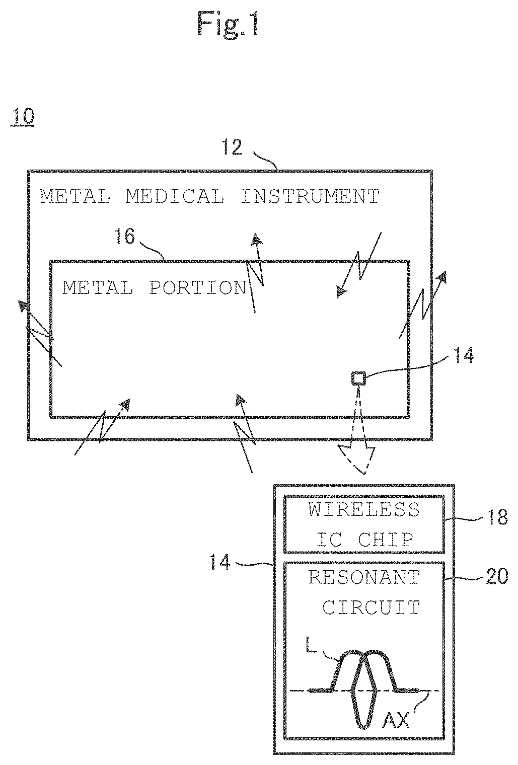
Wireless IC tag-attached metal medical instrument
a metal medical instrument and wireless ic tag technology, applied in the direction of instruments, transformers/reacts, mounting/support/suspension, etc., can solve the problems of increasing the communication distance, reducing the communication distance of the wireless ic tag-attached metal medical instrument, etc., and achieve the effect of improving the degree of freedom in the method of attaching the wireless ic tag
- Summary
- Abstract
- Description
- Claims
- Application Information
AI Technical Summary
Benefits of technology
Problems solved by technology
Method used
Image

Examples
first example
[0075][Configuration of Wireless IC Tag-Attached Metal Medical Instrument]
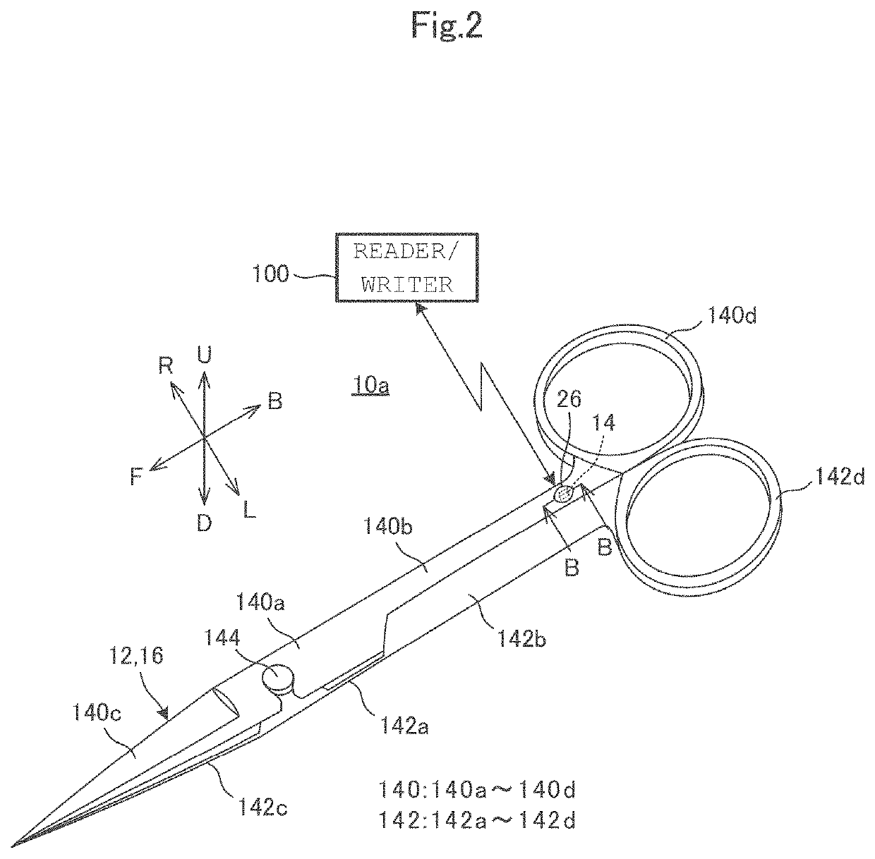
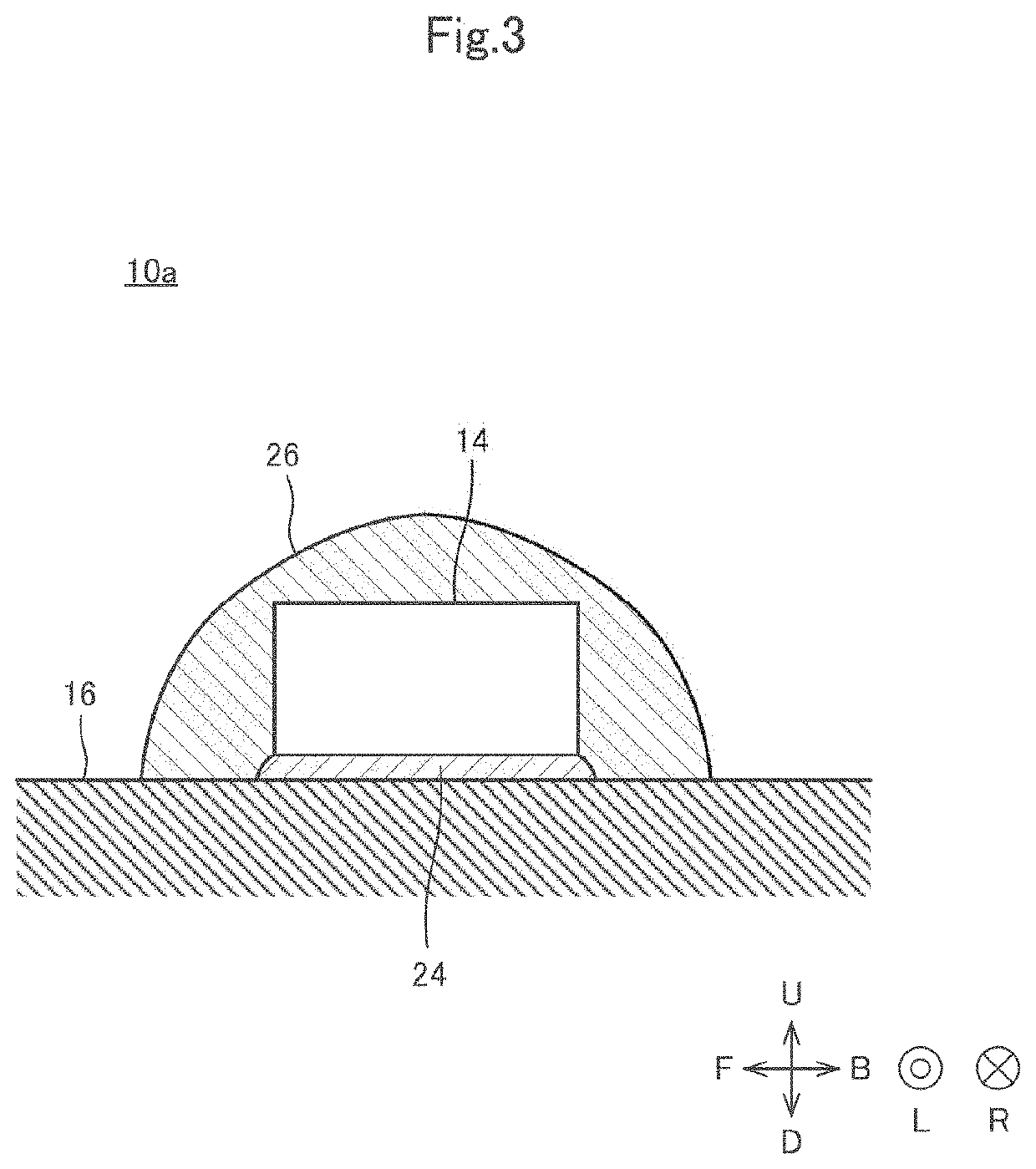
[0076]Next, a wireless IC tag-attached metal medical instrument 10a according to a first example will be described with reference to the drawings. FIG. 2 is an external perspective view of the wireless IC tag-attached metal medical instrument 10a according to the first example. FIG. 3 is a cross-sectional view taken along line B-B in FIG. 2. FIG. 4 is a perspective view of the wireless IC tag 14. FIG. 5 is an equivalent circuit diagram of the wireless IC tag 14.
[0077]Hereinafter, a front-back direction of the wireless IC tag-attached metal medical instrument 10a is referred to as the front-back direction. The front-back direction is a direction in which blades of scissors as the wireless IC tag-attached metal medical instrument 10a extend. An up-down direction of the wireless IC tag-attached metal medical instrument 10a is referred to as the up-down direction. The up-down direction is a direction in which the ...
second example
[0099]Next, a wireless IC tag-attached metal medical instrument 10b according to a second example will be described with reference to the drawings. FIG. 6 is an external perspective view of the wireless IC tag 14 of the wireless IC tag-attached metal medical instrument 10b according to a second modification of the exemplary embodiment.
[0100]As shown, the wireless IC tag-attached metal medical instrument 10b is different from the wireless IC tag-attached metal medical instrument 10a in terms of a method for fixing the wireless IC tag 14. More specifically, the wireless IC tag 14 is fixed to the metal portion 16 by welding in the wireless IC tag-attached metal medical instrument 10b. The wireless IC tag 14 is fixed to the first shaving member 140 or the second shaving member 142 by welding. The wireless IC tag-attached metal medical instrument 10b includes fixing members 200a and 200b. Then, the wireless IC tag 14 is fixed to the first shaving member 140 or the second shaving member 1...
PUM
 Abstract
Description
Claims
Application Information