Elevator control device

a control device and elevator technology, applied in elevators, transportation and packaging, etc., can solve the problems of unbalance torque, affecting the stability of the elevator, so as to reduce the calculation load and suppress the influence of unbalance torque. , the effect of sufficient responsiveness

Pending Publication Date: 2022-05-05
MITSUBISHI ELECTRIC CORP
View PDF0 Cites 0 Cited by
  • Summary
  • Abstract
  • Description
  • Claims
  • Application Information

AI Technical Summary

Benefits of technology

[0010]The present invention is made in accordance with such a new finding obtained this time that the elevator control device according to the present invention, in particular, the unbalance torque estimation unit can estimate the unbalance torque based on the first time period from the output change of the brake state command signal for switching the brake operation state from the braking state to the releasing state to the time when the motor starts the rotating operation along with the release of the brake, and on the positive or negative sign of

Problems solved by technology

This configuration causes a problem in that, when running of the elevator is started, the car and the counterweight are unbalanced in weight.
At the timing at which the brake is released, abrupt state variations of the car are liable to occur.
It is well known that the abrupt state variations of the car are caused by an unbalance torque in the motor due to a weight difference between the car and the counterweight.
This unbalance torque acts as a stepped input disturbance to the motor along with the brake release, thereby causing the abrupt state variations of the car.
That is, the elevator control device detects a load weight of the car through use of a scale being a load detection device, and first estimates an unbalance torque at this time.
However, this system requires the load detection device.
Therefore, there has been a problem of an increase in cost.
Further, at the time of installation of the elevator, work related to mou

Method used


Image

  • Elevator control device
  • Elevator control device
  • Elevator control device

Examples


first embodiment

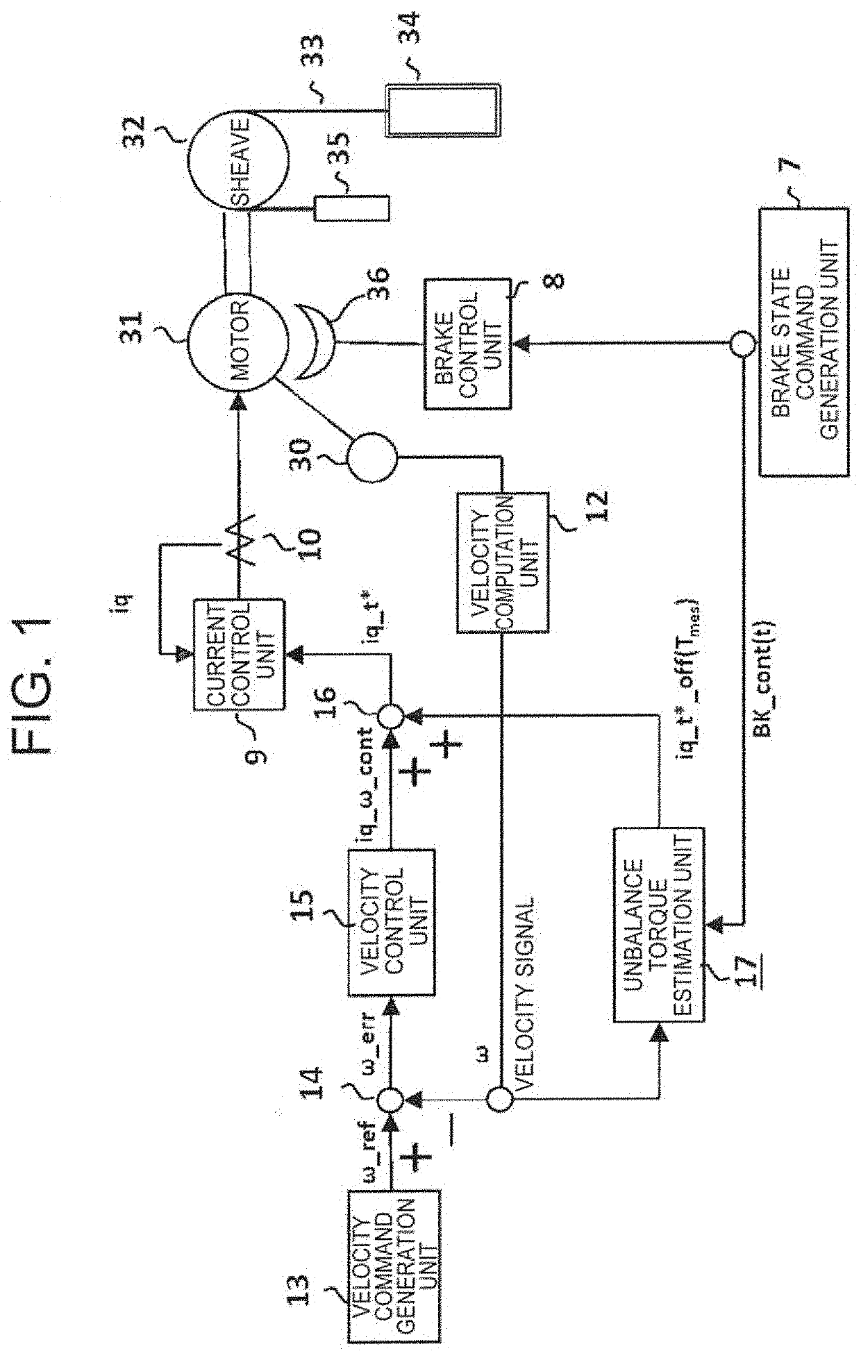
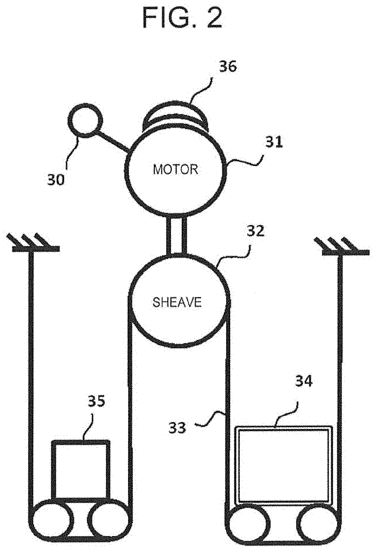
[0026]FIG. 1 is a diagram for illustrating a configuration of an elevator control device according to a first embodiment of the present invention. A sheave 32 is connected to a rotary shaft of a motor 31. A rope 33 is looped around the sheave 32. The rope 33 has one end connected to a car 34, and the other end connected to a counterweight 35. As a result, the car 34 and the counterweight 35 are suspended through use of the rope 33 in a traction system with respect to the sheave 32. The rope 33 is not limited to a rope having a circular cross section, and includes, for example, a rope having a belt shape. An encoder 30 configured to detect an angle is connected to the motor 31 to which the sheave 32 is connected. With this encoder 30, angle information related to a rotational angle of the motor 31 can be obtained. A velocity control system is formed based on this angle information.

[0027]In this case, an elevator mechanical system is formed of components denoted by reference symbols 3...

second embodiment

[0069]The elevator control device according to the first embodiment of the present invention has a configuration effective with respect to a case in which, for example, the characteristic of the brake 36 is not greatly changed. In contrast, an elevator control device according to a second embodiment of the present invention is configured to suppress the start shock and the rollback to be small even when, while the elevator system is in operation, the characteristic of the brake 36 is changed by being affected by temperature or the like.

[0070]FIG. 9 is a diagram for illustrating the elevator control device according to the second embodiment of the present invention. The elevator control device according to the second embodiment of the present invention is directed to an elevator control device assuming a case in which the brake 36 has a characteristic change. In FIG. 9, a part of the unbalance torque estimation unit 17 in the first embodiment illustrated in FIG. 1 is replaced with an...


PUM


Abstract

Proposed is an elevator control device in which an unbalance torque estimation unit configured to estimate an unbalance torque in a motor is implemented in accordance with such a new finding that the unbalance torque can be estimated based on a first time period from an output change of a brake state command signal for switching an operation state of a brake from a braking state to a releasing state to a time when the motor starts a rotating operation along with release of the brake, and on a positive or negative sign of a velocity signal obtained when the motor starts rotation. As a result, as compared to the related art, a smaller calculation load can be achieved. Further, the elevator control device can have a sufficient responsiveness for suppressing an influence of the unbalance torque.

Description

TECHNICAL FIELD[0001]The present invention relates to an elevator control device configured to reduce abrupt state variations of a car of an elevator, which occur when running of the elevator is started.BACKGROUND ART[0002]In a general rope-type elevator, a car and a counterweight are each suspended by a rope in a traction system with respect to a sheave. This configuration causes a problem in that, when running of the elevator is started, the car and the counterweight are unbalanced in weight. When the car stays at a landing floor, the car is kept under a stationary state through use of a brake. Then, when the running of the car is to be started, an elevator control device first releases the brake. Next, after the brake is released, a motor rotates the sheave, and thus the car starts a running operation. At the timing at which the brake is released, abrupt state variations of the car are liable to occur. Accordingly, from the viewpoint of ride comfort of passengers, in the elevator...

Claims


Application Information

Patent Timeline
IPC IPC(8): B66B1/30B66B1/32
CPCB66B1/304B66B1/32B66B1/30
Inventor KIMURA, TETSUYAYOKOYAMA, EIJIBABA, TOSHIYUKIOTSUKA, YASUSHI
Owner MITSUBISHI ELECTRIC CORP
Why Eureka
Try Eureka