Method of design of fuel cell fluid flow networks

a technology of fluid flow and fuel cell, applied in the direction of fuel cells, electrical appliances, electrochemical generators, etc., can solve the problems of inefficient fc stack performance, narrow or completely blocked cooling channels, and inconvenient design of fuel cell fluid flow networks, so as to reduce computational efforts

Pending Publication Date: 2022-05-05
TOYOTA MOTOR ENGINEERING & MANUFACTURING NORTH AMERICA
View PDF1 Cites 1 Cited by
  • Summary
  • Abstract
  • Description
  • Claims
  • Application Information

AI Technical Summary

Benefits of technology

[0015]Compared with explicit topology optimization methods, the one or more dehomogenization-based methods set forth, described, and / or illustrated herein decouples the numerical mesh / grid resolution required during optimization with the final explicit design. In the porous media optimization stage, where multiphysics finite element analysis is conducted, relatively coarse mesh discretization can be used to drastically reduce the computational effort. In the subsequent dehomogenization stage, the domain mesh discretization is refined to extract intricate explicit channels.

Problems solved by technology

In such configurations, however, the coolant channels are very narrow or completely blocked, while in other regions the coolant channels are wide and open.
This may lead to non-uniform cooling throughout the FC stack, and consequently, inefficient FC stack performance.
The use of inverse design methods for designing FC bipolar plates, however, has been limited to a single layer configuration.
Contemporary design methods generally use explicit topology optimization, which are inevitably expensive in computation.

Method used


Image

  • Method of design of fuel cell fluid flow networks
  • Method of design of fuel cell fluid flow networks
  • Method of design of fuel cell fluid flow networks

Examples


examples

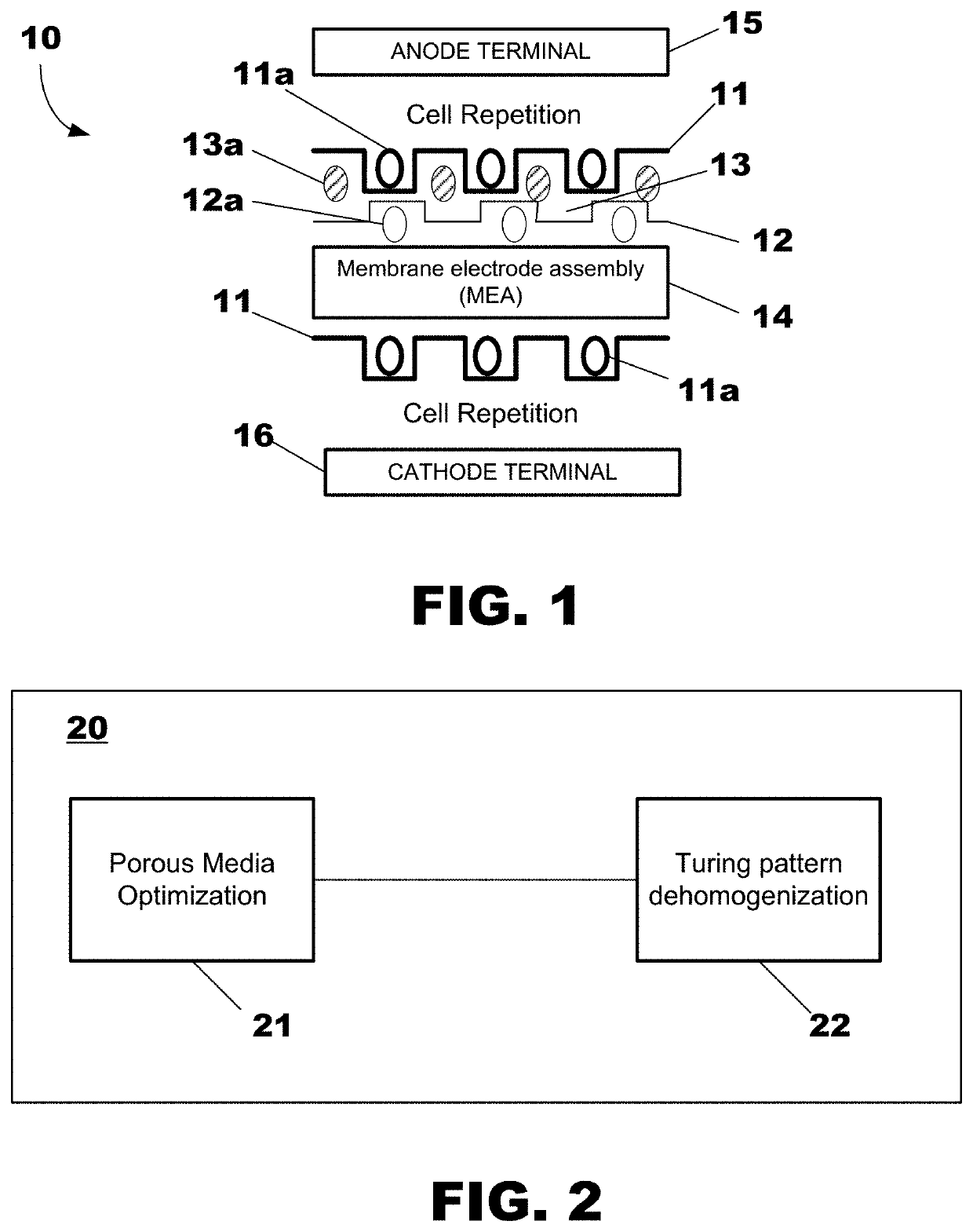
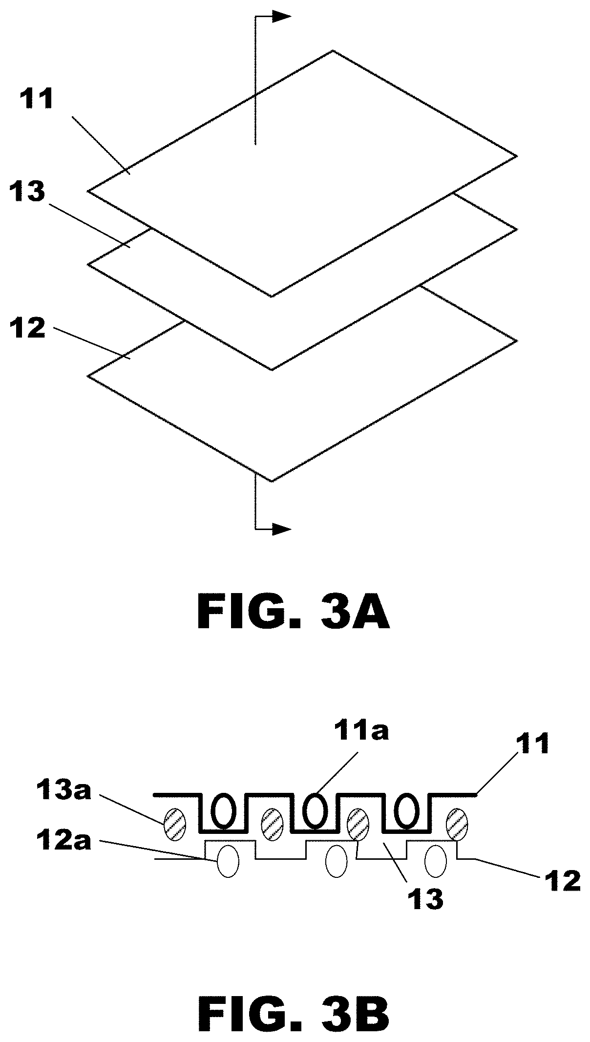
[0078]To demonstrate the proposed method, a multi-layer FC design example is used. FIG. 5 illustrates an example of design and analysis domains at the air layer 11, the hydrogen layer 12, and the coolant layer 13. Design fields ϕ(a) and ϕ(h) are assigned to the air domain D(a) and the hydrogen domain D(h). As illustrated in FIG. 5, at the air layer 11, air is supplied from the upper right inlet. At the hydrogen layer 12, hydrogen is supplied from the upper left inlet. Air and hydrogen travel across the entire plate before leaving the system through the outlets located at opposite corners. Such cross-flow configuration is designed to facilitate the mixture of reactants.

[0079]At the coolant layer 13, coolant flows in the same direction as the air flow. Coolant enters the FC stack from the middle right inlet, and leaves the system via the middle left outlet. Since the hydrogen supply is often sufficient due to its high concentration, the reaction rate inside FC stacks is dominated by t...


PUM

PropertyMeasurementUnit
microstructuresaaaaaaaaaa
permeabilityaaaaaaaaaa
diffusion coefficientaaaaaaaaaa

Abstract

One or more methods of obtaining an optimal design of a fuel cell having fluid flow networks. In one or more methods, air, hydrogen, and coolant flow networks are simultaneously designed using porous media optimization and Turing pattern dehomogenization.

Description

TECHNICAL FIELD[0001]Embodiments relate generally to one or more methods of obtaining an optimal design of a fuel cell (FC) having fluid flow networks. In particular, embodiments relate to one or more methods of simultaneously designing air, hydrogen, and coolant flow networks in FC bipolar plates using porous media optimization and Turing-pattern dehomogenization.BACKGROUND[0002]Hydrogen fuel cell (FC) technology has been utilized widely in a variety of stationary and non-stationary applications, e.g., space transport, satellites, motor vehicles, power generation, and electronics. The FC device converts chemical potential energy into electrical energy.[0003]A FC stack generally comprises hundreds of FCs arranged in a stack formation. Each individual FC in the stack may have a structure comprising a membrane electrode assembly (MEA) which is interposed between plates representing electrodes. The MEA is as a pro-ton exchange membrane (PEM) cell having sides coated with a catalyst for...

Claims


Application Information

Patent Timeline
Patent Type & Authority Applications(United States)
IPC IPC(8): H01M8/2404H01M8/0258H01M8/0267
CPCH01M8/2404H01M8/0267H01M8/0258Y02E60/50H01M8/04291H01M8/04835H01M8/04992
Inventor ZHOU, YUQINGDEDE, ERCAN M.NOMURA, TSUYOSHI
Owner TOYOTA MOTOR ENGINEERING & MANUFACTURING NORTH AMERICA
Why Eureka
Try Eureka