Loop thermosyphon devices and systems, and related methods

a technology of thermosyphon and loop, which is applied in the direction of liquid cooling, lighting and heating apparatus, cooling/ventilation/heating modifications, etc., can solve the problems of incumbent technology reaching its limits with devices with very high power and power density, and prior heat-pipes and thermosyphons do not incorporate or rely on mechanical pumps. , to achieve the effect of low thermal resistan

Pending Publication Date: 2022-05-05
DEEIA INC
View PDF1 Cites 1 Cited by
  • Summary
  • Abstract
  • Description
  • Claims
  • Application Information

AI Technical Summary

Benefits of technology

[0006]A loop thermosyphon can combine the best of heat-pipes and traditional liquid-cooling systems that include a mechanical pump. Like a heat pipe, a thermosyphon is passive, and like a pumped liquid loop, a loop thermosyphon can transport heat over a long distance due to an ultra-low thermal resistance provided by two-phase heat transfer. And, using a selected working fluid, even the small available

Problems solved by technology

On the other hand, some prior heat-pipes and thermosyphons do not incorporate or rely on a mechanical pump to urge the heat-transfer fluid thr

Method used


Image

  • Loop thermosyphon devices and systems, and related methods
  • Loop thermosyphon devices and systems, and related methods
  • Loop thermosyphon devices and systems, and related methods

Examples


Embodiment Construction

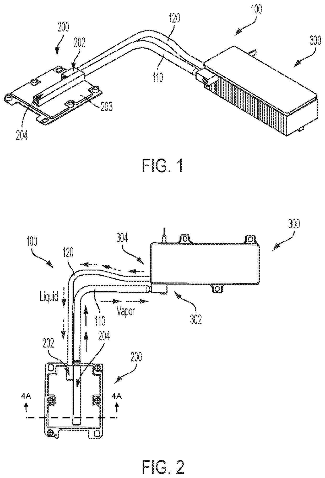
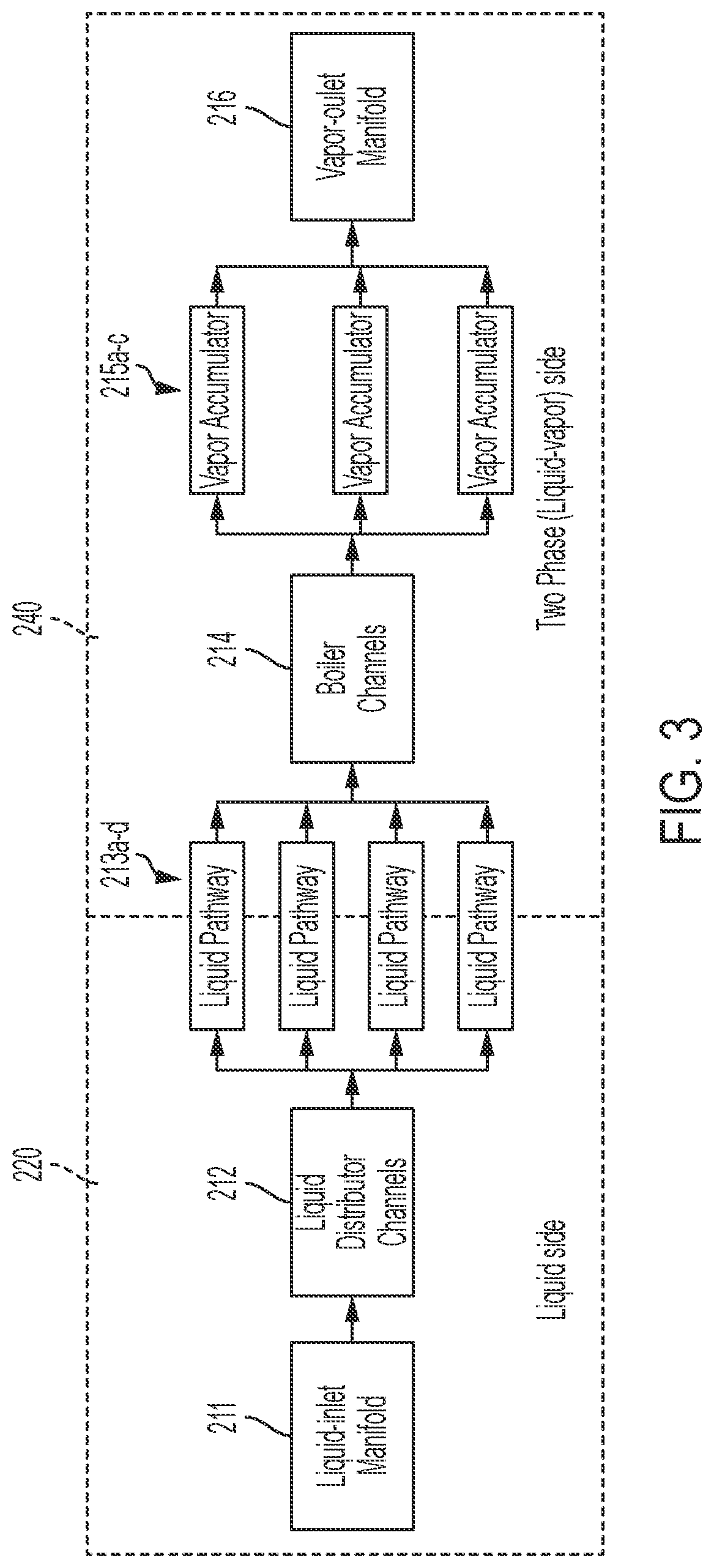
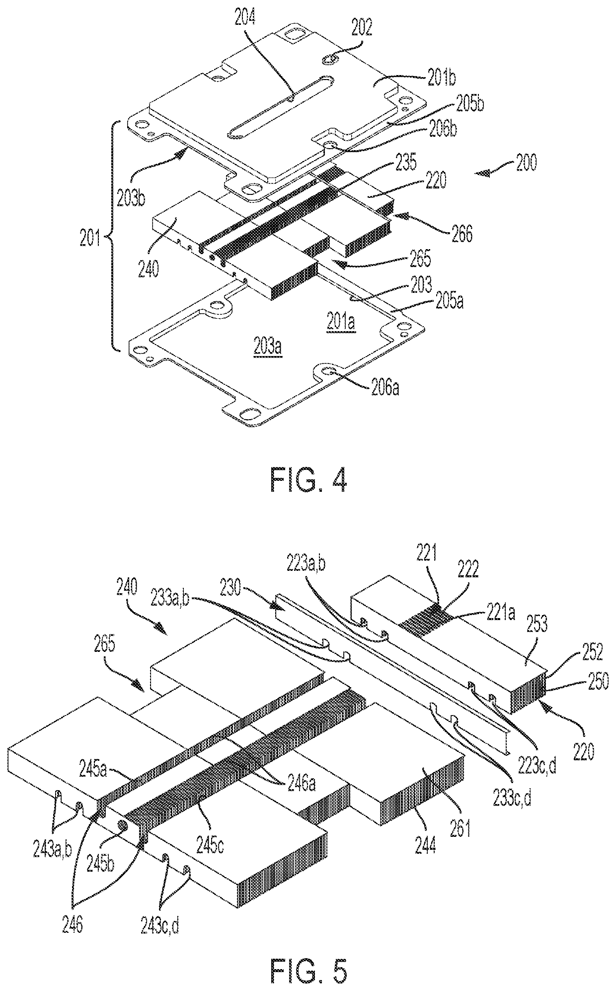
[0080]The following describes various principles related to loop thermosyphons. For example, certain aspects of disclosed principles pertain to evaporator features and certain other aspects pertain to features of conduits coupling an evaporator with a condenser. And still other aspects pertain to systems that such loop thermosyphons. That said, descriptions herein of specific apparatus configurations and combinations of method acts are but particular examples of contemplated features chosen as being convenient illustrative examples of disclosed principles. One or more of the disclosed principles can be incorporated in various other components and systems to achieve any of a variety of corresponding functional characteristics.

[0081]Thus, components and systems having attributes that are different from those specific examples discussed herein can embody one or more presently disclosed principles, and can be used in applications not described herein in detail. Accordingly, such alterna...


PUM


Abstract

A loop thermosyphon can combine the best of heat-pipes and traditional liquid-cooling systems that include a mechanical pump. A disclosed heat-transfer device includes a first heat-transfer component and a second heat-transfer component fluidly coupled with each other by a first conduit and a second conduit. A first manifold is positioned in the first heat-transfer component and defines a first plurality of liquid pathways. The first manifold fluidly couples with the first conduit. A second manifold is also positioned in the first heat-transfer component and defines a second plurality of liquid pathways fluidly coupled with and extending from the first plurality of liquid pathways. The second manifold further defines a plurality of boiling channels, a plurality of accumulator channels and a vapor manifold. The boiling channels extend transversely relative to and are fluidly coupled with the second plurality of liquid pathways. The plurality of accumulator channels extends transversely relative to and are fluidly coupled with the plurality of boiling channels. The vapor manifold is configured to collect vapor from one or more of the plurality of boiling channels, one or more of the plurality of accumulator channels, or both. The first heat-transfer component further defines an outlet fluidly coupling the vapor manifold with the second conduit. Electrical devices incorporating such a heat-transfer device also are disclosed, as well as associated methods.

Description

FIELD[0001]This application and the subject matter disclosed herein (collectively referred to as the “disclosure”), generally concern devices and systems for facilitating heat transfer, and related methods. More particularly, but not exclusively, this disclosure pertains to loop thermosyphon devices and systems, and related methods, for cooling one or more heat-dissipating components, such as, for example, an electrical device.BACKGROUND INFORMATION[0002]Many industrial processes, consumer goods, power generators, combustion chambers, communication devices, electronic components, electrical storage components (e.g., batteries), etc., and associated systems, rely on heat transfer to function as intended. For example, some rely on cooling (e.g., radio transmitters) and others rely on heating (e.g., endo-thermic chemical reactions) to maintain a temperature within a specified range between an upper threshold temperature and a lower threshold temperature.[0003]The prior art has responde...

Claims


Application Information

Patent Timeline
IPC IPC(8): H05K7/20
CPCH05K7/20327H05K7/20245H05K7/20318H05K7/20309H05K7/20336F28D15/0275F28D15/0266F28D15/043
Inventor POKHARNA, HIMANSHUTAN, GIN HWEE
Owner DEEIA INC
Why Eureka
Try Eureka