Plastic optical fiber core diameter measuring method, plastic optical fiber core diameter measuring apparatus used therefor, plastic optical fiber defect detecting method, and plastic optical fiber defect detecting apparatus used therefor

a technology of plastic optical fiber and core diameter, which is applied in the direction of measurement devices, instruments, structural/machine measurement, etc., can solve the problems of inability to measure the diameter of the formed core, and inability to ensure uniform quality

Pending Publication Date: 2022-05-12
NITTO DENKO CORP
View PDF0 Cites 0 Cited by
  • Summary
  • Abstract
  • Description
  • Claims
  • Application Information

AI Technical Summary

Problems solved by technology

Unfortunately, if an apparatus for manufacturing the POFs is continuously operated for a long time, there are cases in which it is difficult to ensure uniform quality.
This apparatus is capable of judging whether the core has defects (foreign mat...

Method used


Image

  • Plastic optical fiber core diameter measuring method, plastic optical fiber core diameter measuring apparatus used therefor, plastic optical fiber defect detecting method, and plastic optical fiber defect detecting apparatus used therefor
  • Plastic optical fiber core diameter measuring method, plastic optical fiber core diameter measuring apparatus used therefor, plastic optical fiber defect detecting method, and plastic optical fiber defect detecting apparatus used therefor
  • Plastic optical fiber core diameter measuring method, plastic optical fiber core diameter measuring apparatus used therefor, plastic optical fiber defect detecting method, and plastic optical fiber defect detecting apparatus used therefor

Examples


examples

[0078]The present disclosure will be described hereinafter in further detail using examples and comparative examples. The present disclosure is not limited to the examples to be described below within the scope of the present disclosure.

example 6

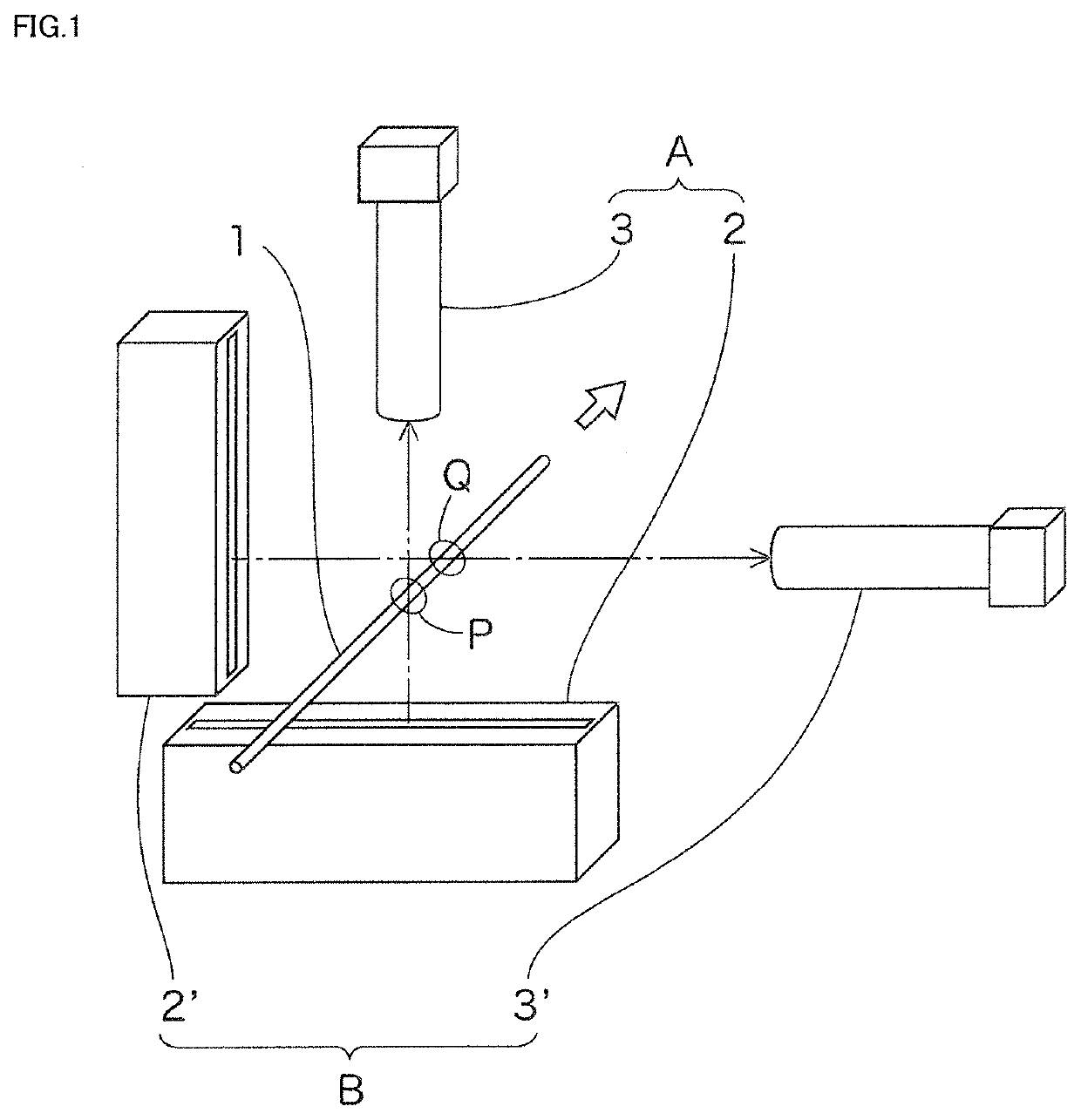
[0088]Next, the apparatus shown in FIG. 7 was used to measure the diameter and eccentricity of the core (with reference to FIG. 3) of the POF 1 in an in-line fashion ten times at different measurement locations. The apparatus of FIG. 7 is similar in configuration (the light emission width and the like) to that in Example 2 except that the imaging unit C is added. The same POF 1 to be measured is used as in Example 2. Results of comparison between the obtained diameter and eccentricity of the core 4 and the actually measured diameter and eccentricity of the core 4 are shown in FIGS. 9 and 10.

[0089]As a result of the comparison, the maximum difference in diameter of the core 4 was 2.2 μm, and the maximum difference in eccentricity of the core 4 was 1.6 μm.

[0090]The actually measured diameter and eccentricity of the core 4 were determined in the following manner. Specifically, an area of the POF 1 where the diameter and eccentricity of the core 4 were measured is actually cut and polis...

example 7

[0091]The apparatus shown in FIG. 1 was used to measure the diameter and eccentricity of the core 4 (with reference to FIG. 3) of the POF 1 in the same manner as in Example 6 except that the measurement was made at four locations. Results of comparison between the obtained diameter and eccentricity of the core 4 and the actually measured diameter and eccentricity of the core 4 are shown in FIGS. 11 and 12.

[0092]As a result of the comparison, the maximum difference in diameter of the core 4 was 2.9 μm, and the maximum difference in eccentricity of the core 4 was 3.3 μm.


PUM


Abstract

The present disclosure relates to a plastic optical fiber (POF) core diameter measuring method and a POF core diameter measuring apparatus, and a POF defect detecting method, and a POF defect detecting apparatus used therefor. Light irradiation mechanisms are provided for irradiating a side of a POF with light, with imaging mechanisms provided on the opposite side of the POF from the light irradiation mechanisms; and a data processing mechanism for processing image data on the POF acquired from the imaging mechanisms to calculate the core diameter of the POF. The ratio (D/W) of the shortest distance D to a light emission width W is in the range of 0.9 to 1.3 where W is the light emission width of the light irradiation mechanisms and D is the shortest distance between a light emission position of the light irradiation mechanisms and the side of the POF.

Description

TECHNICAL FIELD[0001]The present disclosure relates to a method of measuring the core diameter of a plastic optical fiber (referred to hereinafter as a “POF” in some cases) used for communication applications and the like, a POF core diameter measuring apparatus used therefor, a POF defect detecting method, and a POF defect detecting apparatus used therefor. More particularly, the present disclosure relates to a method and apparatus that are capable of continuously measuring the core diameter of a POF in an in-line fashion in the steps of manufacturing the POF, and a method and apparatus that are capable of detecting defects in the POF.BACKGROUND ART[0002]Demand for POFs has been increasing in recent years because the POFs which are made of plastic are lightweight, have good flexibility, and can be manufactured at low costs. In general, such POFs are manufactured by melt extrusion or by a method of melt-heating and drawing preforms by means of an interfacial gel polymerization proce...

Claims


Application Information

Patent Timeline
IPC IPC(8): G01M11/02G01B11/08
CPCG01M11/0257G01B11/08G01B11/12
Inventor SAKAMOTO, MASARUSUEHIRO, ICHIRO
Owner NITTO DENKO CORP
Why Eureka
Try Eureka