Eye accommodation distance measuring device and method for head-mounted display, and head-mounted display

a distance measurement and display technology, applied in the field of stereoscopic displays, can solve the problems of destroying the rendered picture, affecting the matching process of real and virtual objects, and affecting the user's visual comfort,

Pending Publication Date: 2022-05-19
SAMSUNG ELECTRONICS CO LTD
View PDF0 Cites 3 Cited by
  • Summary
  • Abstract
  • Description
  • Claims
  • Application Information

AI Technical Summary

Benefits of technology

[0027]The interferometer may include a laser array including a plurality of lasers, a laser array driver configured to supply each laser of the laser array with a frequency-modulated control signal, a detector, a beam-splitter, and a reference mirror, and the interferomet...

Problems solved by technology

In commercial AR/VR systems, having fixed focal length, these values cannot be matched, which causes so called vergence-accommodation conflict (VAC) and, as a result, fatigue and visual discomfort for a user.
When using AR-glasses, VAC effect significantly complicates a process of matching real and virtual objects since when observing the real object, the virtual object may be defocused.
Further, there is a problem of defocusing due to eye movement.
In conventional AR/VR systems eye movement lead to a destruction of a rendered picture.
One of the main augmented reality (AR) systems problems is focus matching for real and artificial objects.
If virtual images co-located with real world objects are in di...

Method used


Image

  • Eye accommodation distance measuring device and method for head-mounted display, and head-mounted display
  • Eye accommodation distance measuring device and method for head-mounted display, and head-mounted display
  • Eye accommodation distance measuring device and method for head-mounted display, and head-mounted display

Examples


first embodiment

[0087]FIG. 9 depicts schematic diagram of an eye accommodation distance determining device according to an embodiment of the disclosure.

[0088]Referring to FIG. 9, the interferometer of the eye accommodation distance determining device is a self-mixing interferometer (SMI) and comprises a laser array 11, for example, an array of vertical-cavity surface-emitting lasers (VCSEL), a laser array driver 12 and an optical system.

[0089]The laser array driver 12 selectively supplies a frequency modulated control signal providing modulation of a laser pump current to lasers of the array, simultaneously to one laser, group of laser or to all the lasers of the laser array 11. A number of simultaneously operating lasers is limited by a maximum allowable laser radiation power safe for the eye. Each laser of the array has specific beam direction which is different from others, is known in advance and depends from a location of the laser of the laser array 11 relative to other parts of the eye accom...

second embodiment

[0095]FIG. 10 depicts schematic diagram of an eye accommodation distance determining device according to an embodiment of the disclosure.

[0096]Referring to FIG. 10, the interferometer of the eye accommodation distance determining device is a two-arm interferometer comprising a laser array 11, a laser array driver 12, a detector 15, a beam splitter 16, a reference mirror 17 and an optical system.

[0097]The laser array, the laser array driver and the optical system correspond to those of the first embodiment and are not described again.

[0098]The second embodiment differs from the first one in a method of generating the interferometric signal. A beam emitted by specific laser of the array is divided by the beam splitter 16 (partially reflecting mirror) into two beams, one of which reflects from the reference mirror 17 and the other one is delivered to the user's eye and reflects from its surfaces. Both beams return to beam splitter 16 and are sent to detector 15 (see FIG. 10), wherein t...

third embodiment

[0100]FIG. 11 depicts schematic diagram of an eye accommodation distance determining device according to an embodiment of the disclosure.

[0101]Referring to FIG. 11, the interferometer of the eye accommodation distance determining device is a self-mixing interferometer and comprises a single laser 18, a laser driver, an optical-mechanical scanning system and an optical system.

[0102]The optical system of the disclosure corresponds to that of the previous embodiments and is not described again.

[0103]Generation of the interferometric signal is performed using self-mixing effect similarly to the first embodiment, namely by measuring laser bias voltage on the driver side or by measuring laser power oscillations using photodiode built in a laser package.

[0104]Optical-mechanical scanning system provides change of the laser beam direction and may be implemented using any state of art light deflecting technique, for example, using a rotational mirrors, Micro-Electro-Mechanical Systems (MEMS) ...


PUM


Abstract

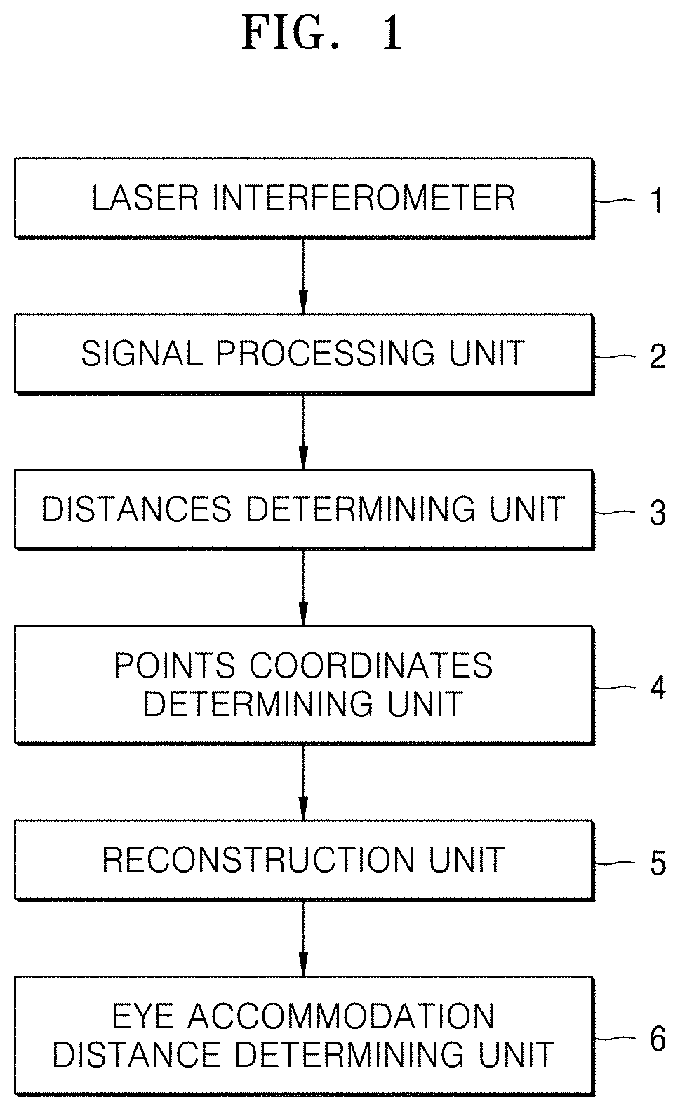
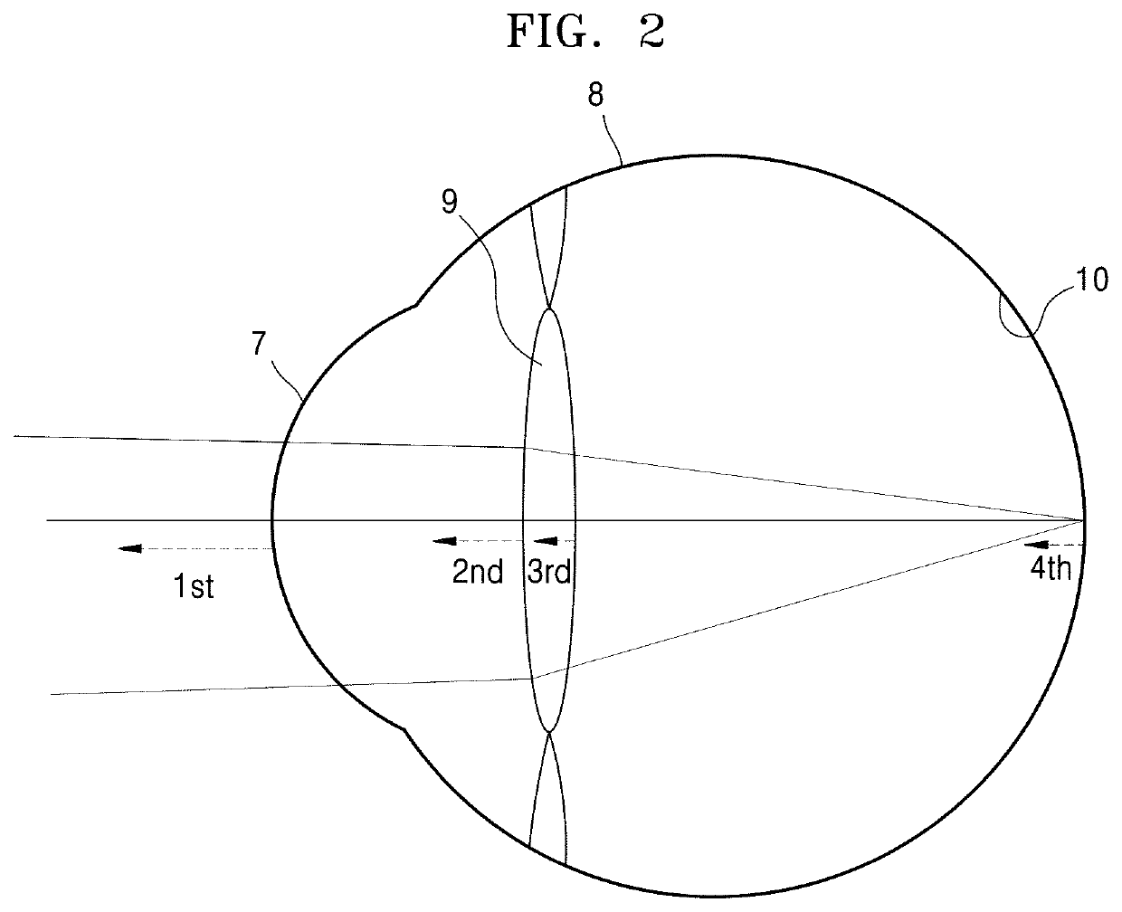
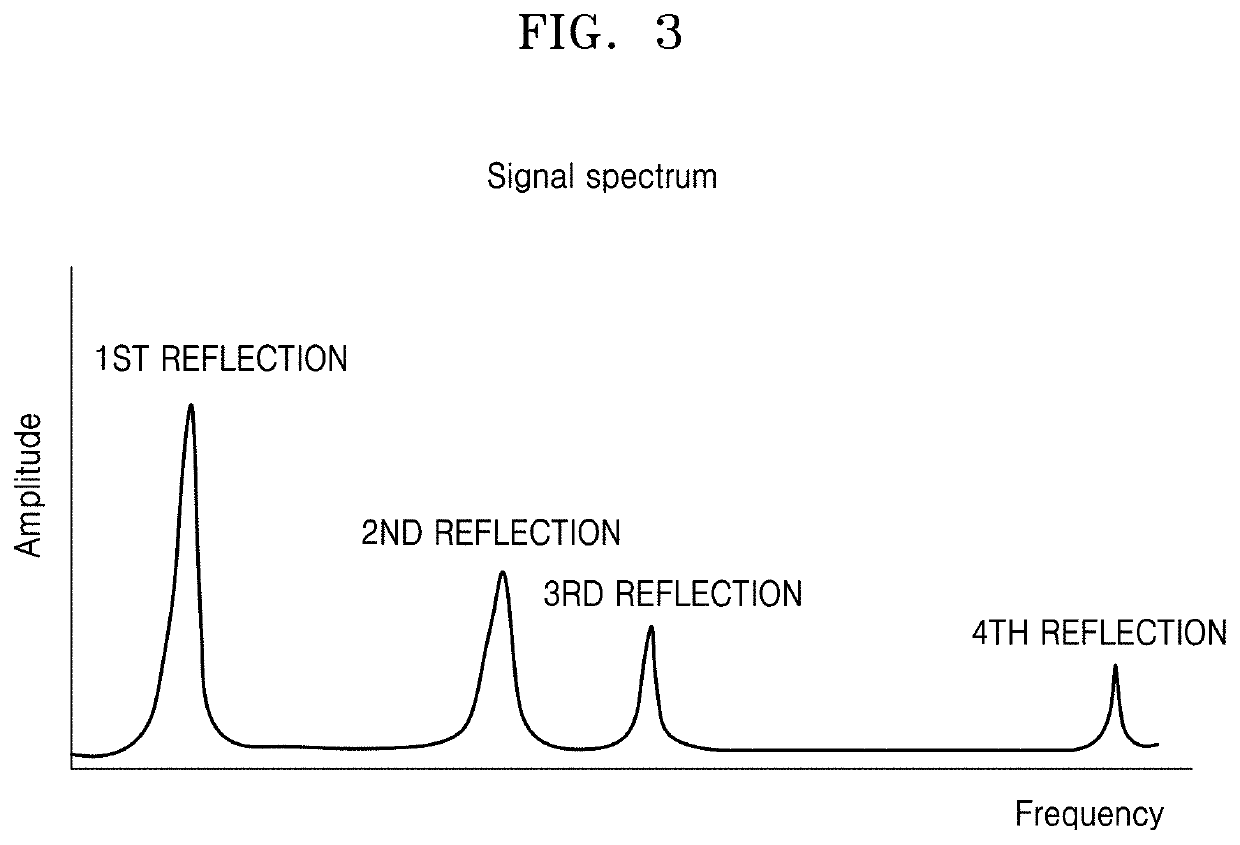
An eye accommodation distance determining device is provided. The eye accommodation distance determining device includes an interferometer configured to generate a plurality of frequency modulated laser beams in different directions and to generate a plurality of interferometric signals using laser beams reflected from eye reflecting surfaces, a signal processer configured to generate a signal spectrum using each of said plurality of interferometric signals, a distance determiner configured to determine distances to the eye reflecting surfaces for each of said plurality of frequency modulated laser beams, a point coordinates determiner configured to determine coordinates of points on each of the eye reflecting surfaces for each of the laser beams, a reconstructor configured to generate an eye inner structure model based on the determined coordinates of points, and an eye accommodation distance determiner configured to determine, based on said eye inner structure model, an eye accommodation distance.

Description

CROSS-REFERENCE TO RELATED APPLICATION(S)[0001]This application is a continuation application, claiming priority under § 365(c), of an International application No. PCT / KR2020 / 008766, filed on Jul. 6, 2020, which is based on and claims the benefit of a Russian patent application number 2019128648, filed on Sep. 12, 2019, in the Russian Intellectual Property Office, and of a Korean patent application number 10-2020-0042405, filed on Apr. 7, 2020, in the Korean Intellectual Property Office, the disclosure of each of which is incorporated by reference herein in its entirety.BACKGROUND1. Field[0002]The disclosure relates to the field of stereoscopic displays. More particularly, the disclosure relates to an eye accommodation distance measuring device and a method for a head-mounted display as well as to corresponding head-mounted display and may be used in augmented / virtual reality systems (AR / VR).2. Description of Related Art[0003]Physiological principles of three dimension (3D) objects...

Claims


Application Information

Patent Timeline
IPC IPC(8): G02B27/01G01B9/02001G01B9/02004G01S17/34G01S7/4915
CPCG02B27/0172G01B9/02007G06T19/006G01S17/34G01S7/4915G01B9/02004G02B27/017G01S17/08G01S7/4916G01S7/4815G01S7/4812G01S7/493G01S17/88A61B3/09G01B9/02092
Inventor LYCHAGOV, VLADISLAV VALERIEVICHSEMENOV, VLADIMIR MIKHAILOVICHSALAMATOVA, EVGENIIA YURIEVNA
Owner SAMSUNG ELECTRONICS CO LTD
Why Eureka
Try Eureka