
Antenna package and image display device including the same

an image display device and antenna package technology, applied in the direction of individual energised antenna arrays, resonant antennas, particular array feeding systems, etc., can solve the problems of circuit wiring damage, signal loss, and signal loss

Pending Publication Date: 2022-05-19
DONGWOO FINE CHEM CO LTD
View PDF7 Cites 0 Cited by
  • Summary
  • Abstract
  • Description
  • Claims
  • Application Information

AI Technical Summary

Benefits of technology

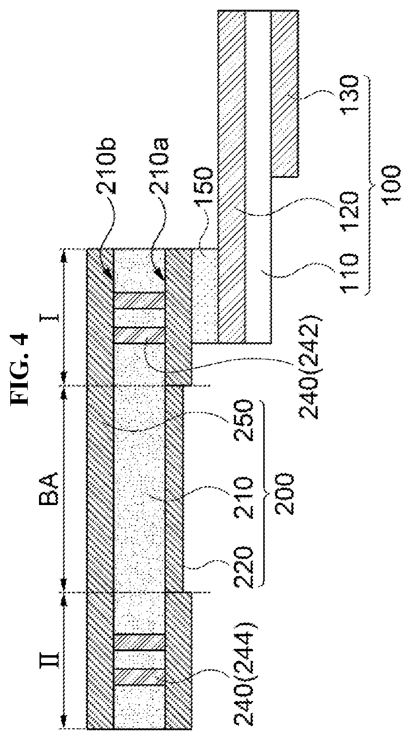
The present invention provides an antenna package with improved mechanical reliability and signaling efficiency in an image display device. This is achieved by including a circuit wiring, ground line, ground layer, and via structure connecting the ground line and ground layer. The via structure improves signal transmission / reception efficiency and prevents signal loss and interference. The via structure is not formed in a bending area of the flexible circuit board to prevent signal loss and deterioration of driving stability. The thickness of signal lines in the bending area is relatively thin to improve bending properties of the flexible circuit board. The ground line is also not formed in the bending area to prevent signal disturbance and signal loss due to damages to the ground line.

Problems solved by technology

However, if a driving frequency of the antenna increases, a signal loss may be increased, and as a length of a transmission path through the circuit board increases, a degree of the signal loss may be further increased.
In this case, a circuit wiring may be damaged, and a bonding failure with the antenna may occur due to a bending stress
Further, as a thickness of an image display device to which the antenna is employed decreases recently, a degree of a bending curvature of the circuit board may also increase.
For example, Korean Published Publication No. 2013-0095451 discloses an antenna integrated into a display panel, but does not suggest the efficient circuit connection as described above.

Method used


Image

  • Antenna package and image display device including the same
  • Antenna package and image display device including the same
  • Antenna package and image display device including the same

Examples


Embodiment Construction

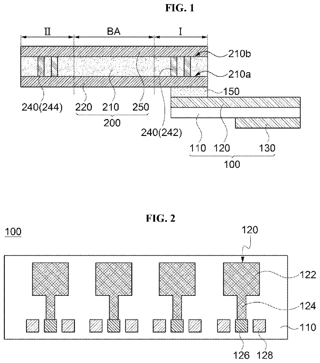
[0035]According to exemplary embodiments of the present invention, there is provided an antenna package in which an antenna device and a flexible circuit board including a ground line are combined. According to exemplary embodiments of the present invention, there is also provided an image display device including the antenna package

[0036]Hereinafter, the present invention will be described in detail with reference to the accompanying drawings. However, those skilled in the art will appreciate that such embodiments described with reference to the accompanying drawings are provided to further understand the spirit of the present invention and do not limit subject matters to be protected as disclosed in the detailed description and appended claims.

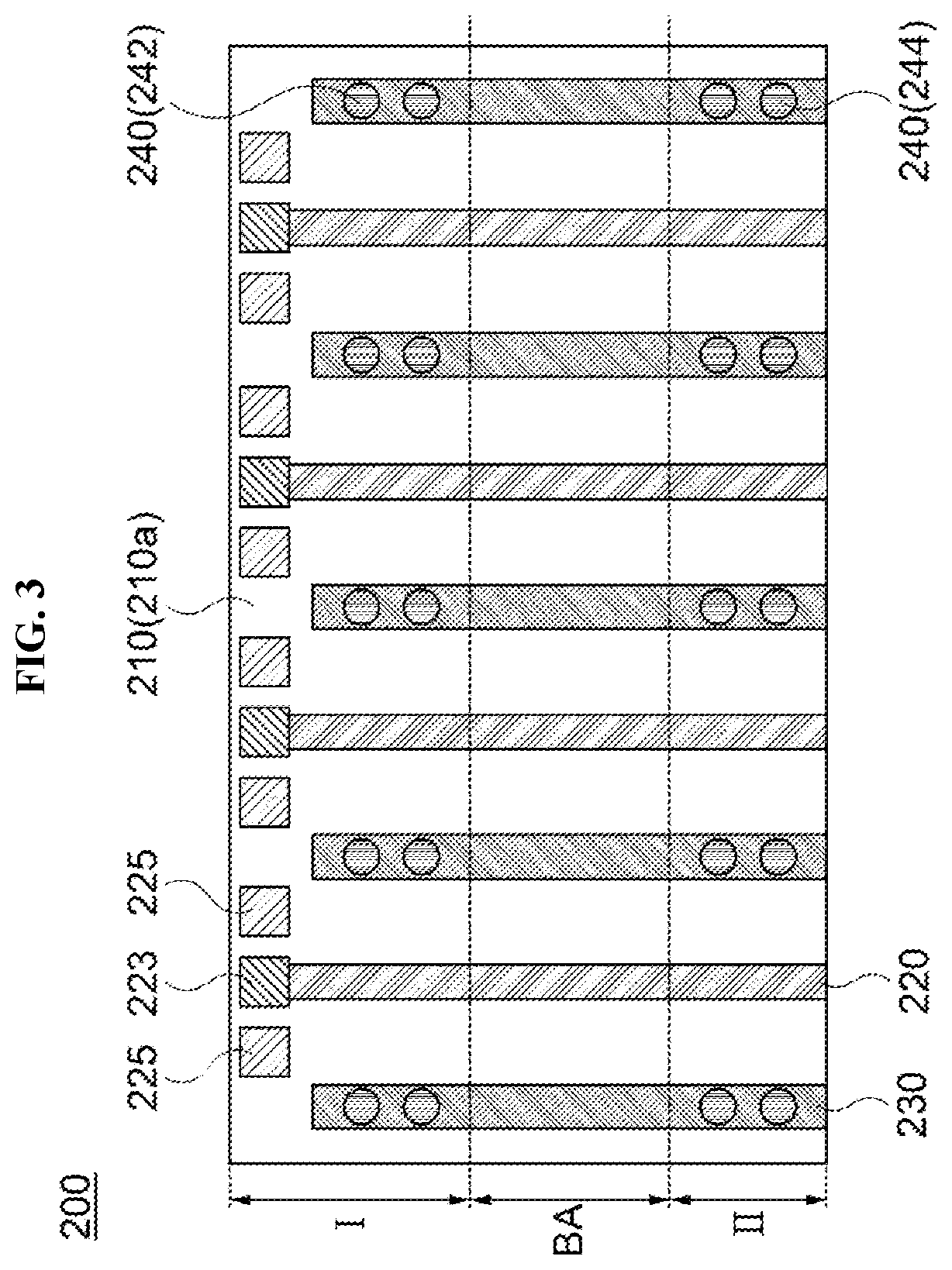
[0037]FIGS. 1 and 2 are a schematic cross-sectional view and a top planar view, respectively, illustrating an antenna package in accordance with exemplary embodiments. Specifically, FIG. 1 is a schematic cross-sectional view illustrating the...


PUM


Abstract

An antenna package according to an embodiment of the present disclosure includes an antenna device including an antenna unit, and a flexible circuit board electrically connected to the antenna unit. The flexible circuit board has a bending area. The flexible circuit board includes a core layer having a first surface and a second surface facing each other, a signal wiring disposed on the first surface of the core layer and electrically connected to the antenna unit, a ground line disposed on the first surface of the core layer to be spaced apart from the signal wiring, a ground layer disposed on the second surface of the core layer, and a via structure penetrating a portion of the core layer in a region excluding the bending area and connecting the ground line and the ground layer with each other.

Description

CROSS-REFERENCE TO RELATED APPLICATION AND CLAIM OF PRIORITY[0001]This application claims priority to Korean Patent Application No. 10-2020-0154537 filed on Nov. 18, 2020 in the Korean Intellectual Property Office (KIPO), the entire disclosures of which are incorporated by reference herein.BACKGROUND1. Field[0002]The present invention relates to an antenna package and an image display device including the same. More particularly, the present invention relates to an antenna package including an antenna device and a circuit board and an image display device including the same.2. Description of the Related Art[0003]As information technologies have been developed, a wireless communication technology such as Wi-Fi, Bluetooth, etc., is combined with an image display device in, e.g., a smartphone form. In this case, an antenna may be combined with the image display device to provide a communication function.[0004]According to developments of a mobile communication technology, an antenna ca...

Claims


Application Information

Patent Timeline
IPC IPC(8): H01Q1/22H01Q1/48
CPCH01Q1/2283H01Q21/08H01Q1/48H01Q1/241H01Q1/38H01Q1/50H01Q1/52H01Q1/22H01Q5/22H01Q21/0006H01Q9/0407
Inventor KIM, NA YEONKIM, YOUNG JULEE, WON HEE
Owner DONGWOO FINE CHEM CO LTD
Learn More