Eureka AIR delivers breakthrough ideas for toughest innovation challenges, trusted by R&D personnel around the world.

Active Suction Cup

Active Publication Date: 2022-05-26
GEKO UNIQUE SUPPORT SYST SL
View PDF9 Cites 2 Cited by
  • Summary
  • Abstract
  • Description
  • Claims
  • Application Information

AI Technical Summary

Benefits of technology

The active suction cup has a vacuum chamber and a way to remove air from inside it. This creates a vacuum that helps the cup stick to surfaces like glass.

Problems solved by technology

These display stands are often unattractive and do not attract the consumer's attention with regard to the product, since they merely use the ceiling or floor as a gripping point.
The configuration and mounting system of the displays are complicated, uncomfortable and require some type of installation, which limits, hinders and makes installation difficult and expensive.
The problem with this type of exhibitors is that the suction cup is fixed by mechanical means and it loses fixation with the surface over time, due to vacuum leakage from the suction cup.
Besides, the weight that the exhibitor tray can support is not big enough to keep objects with weights over 2 Kg for a long time.
Another problem is that the shape of the vacuum chamber does not allow sufficient grip on the surface to which the suction cup is adhered.
Moreover, vacuum generator circuits formed by motors and pumps generate noise during operation, that can be annoying.
To reduce the noise it is possible to use silencers, but these further increase the complexity and size of the suction cup.

Method used


Image

  • Active Suction Cup
  • Active Suction Cup
  • Active Suction Cup

Examples


Embodiment Construction

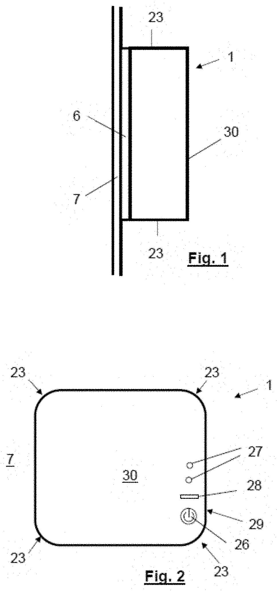
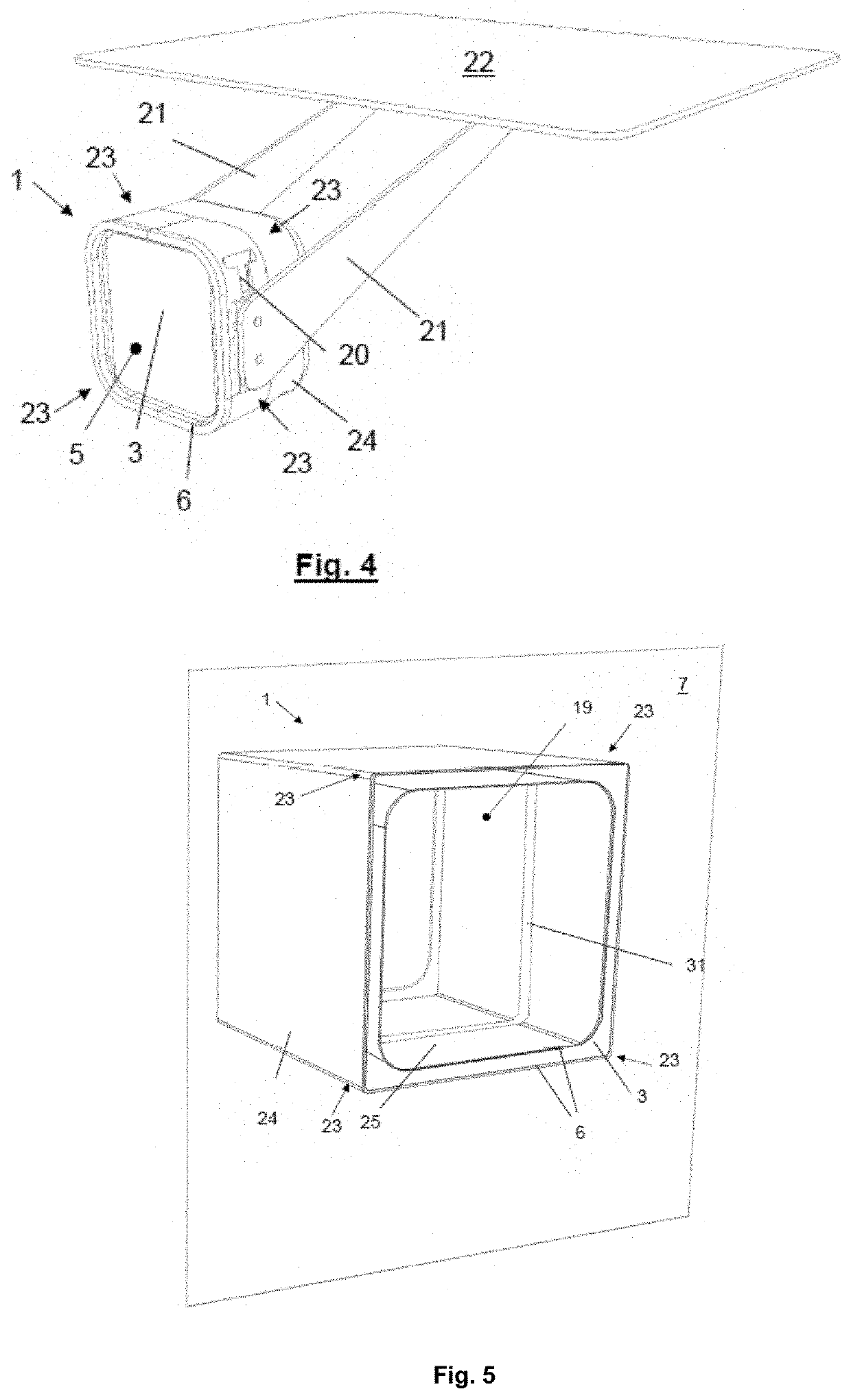
[0013]The active suction cup of the present invention comprises a vacuum chamber and means for extracting air from inside the chamber, acting as a vacuum generating circuit, connected to a duct leading to the outside of the chamber. The vacuum chamber is provided with at least one opening with an elastic rim adapted to be applied against a surface, preferably a smooth, straight surface such as a glass, sealing the vacuum chamber. And the air extraction means are adapted to extract air from inside the vacuum chamber—through the duct—to reduce the pressure inside the chamber so that the suction cup adheres to the surface.

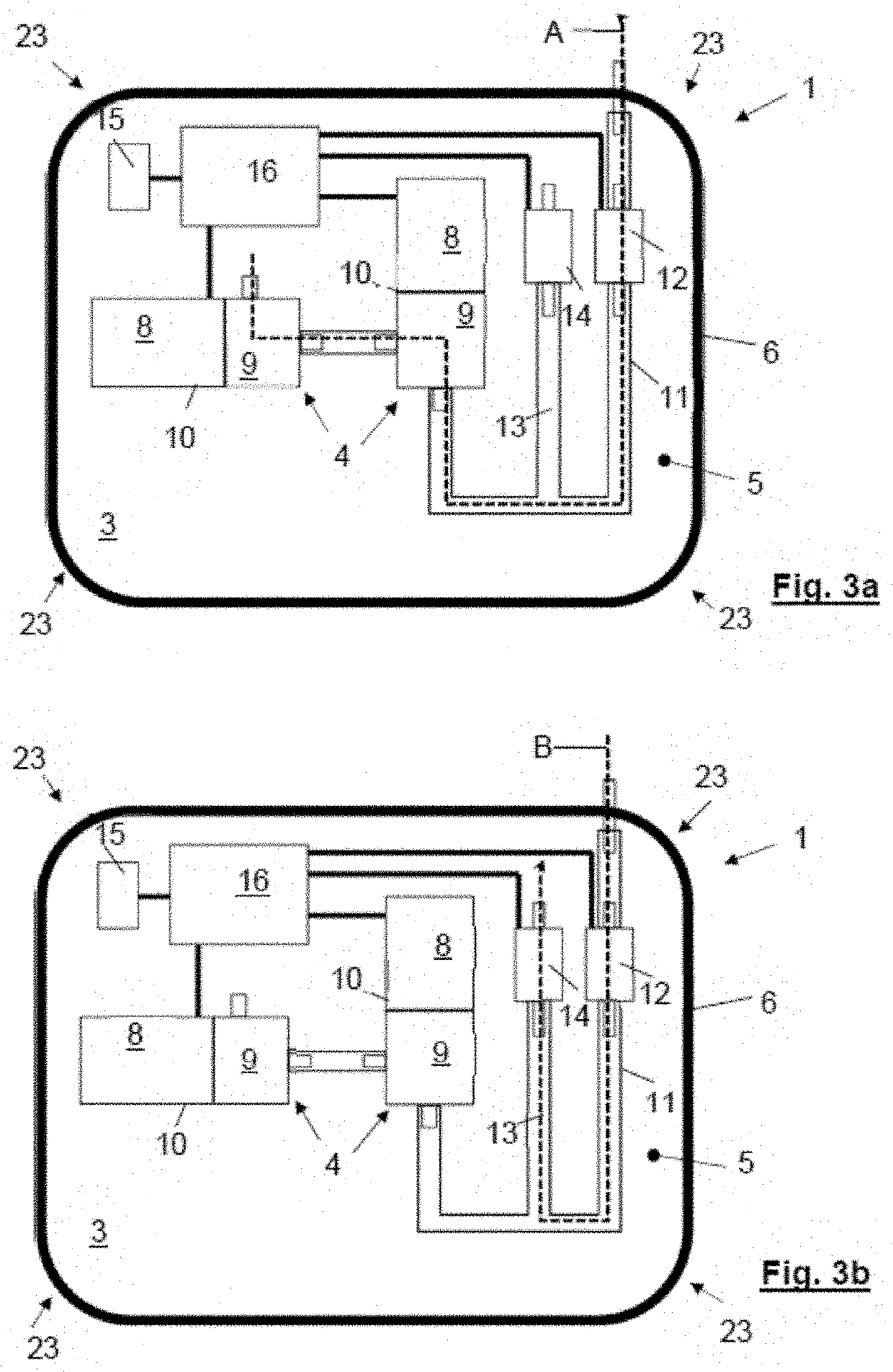
[0014]The duct can be a pneumatic circuit, it does not have to be a simple tube. This conduit or pneumatic circuit interconnects, for example, the motors with the valves (preferably solenoid valves).

[0015]Basically, the active suction cup is characterized in that the air extraction means (comprising motors, solenoid valve(s), pneumatic circuit), i.e. the means forming...


PUM


Abstract

An active suction cup includes a vacuum chamber provided with at least one opening with an elastic rim adapted to be applied against a surface sealingly closing the chamber vacuum, and air extraction means from inside the chamber, adapted to extract the air from inside the chamber to reduce the pressure inside the chamber so that the suction cup remains adhered to the surface. The suction cup is characterized in that the air extraction means are arranged inside the vacuum chamber and connected to a conduit that opens outside the chamber, the suction cup also comprising a pressure sensor inside the chamber to detect the pressure inside the chamber. The pressure sensor is connected to control means adapted to actuate the air extraction means if the pressure detected by the pressure sensor is greater than a predetermined maximum pressure threshold.

Description

CROSS-REFERENCE TO RELATED APPLICATIONS[0001]This application claims priority to and is a continuation-in-part of Spanish utility model application U202032568, filed on Nov. 26, 2020, which granted as ES1261804 on Mar. 8, 2021, the entire contents of each is incorporated by reference.TECHNICAL FIELD OF THE INVENTION[0002]Active suction cup for vacuum gripping, designed for use inside or outside homes and commercial premises, intended for holding all kind of objects, such that the suction cup easily adheres to any smooth surface.BACKGROUND OF THE INVENTION[0003]Currently there are a multitude of display stands, both for advertising and for home, capable of holding a wide variety of objects. These display stands are often unattractive and do not attract the consumer's attention with regard to the product, since they merely use the ceiling or floor as a gripping point. The configuration and mounting system of the displays are complicated, uncomfortable and require some type of installa...

Claims


Application Information

Patent Timeline
IPC IPC(8): F16B47/00
CPCF16B47/00F16M11/041F16M13/022F16M2200/028F16M2200/024
Inventor NOTHMAN, PIERRE MICHEL
Owner GEKO UNIQUE SUPPORT SYST SL
Why Eureka
Eureka Blog
Learn More