Eureka AIR delivers breakthrough ideas for toughest innovation challenges, trusted by R&D personnel around the world.

Tee union ball drain valve

Active Publication Date: 2022-05-26
NIBCO INC
View PDF7 Cites 0 Cited by
  • Summary
  • Abstract
  • Description
  • Claims
  • Application Information

AI Technical Summary

Benefits of technology

The present invention includes a valve assembly and a tee union ball drain valve that can be used in piping systems. The valve assembly has a fluid passageway and a drain path, and includes a first valve member which can open or close the fluid passageway and a second valve member which can open or close the drain path. The tee union ball drain valve has a valve body with a fluid passageway and a drain path, and includes a first and second valve members located at the intersection of the fluid passageway and the drain path, and a tee body with a union end, a first and second fitting ends. The valve and tee body are coupled together, and at least one seal member is located between the valve body and the tee body. This invention provides a more efficient and reliable valve assembly and a more compact piping system.

Problems solved by technology

This creates additional leak paths, takes additional time to assemble, and takes space given the number of components.

Method used


Image

  • Tee union ball drain valve
  • Tee union ball drain valve
  • Tee union ball drain valve

Examples


Embodiment Construction

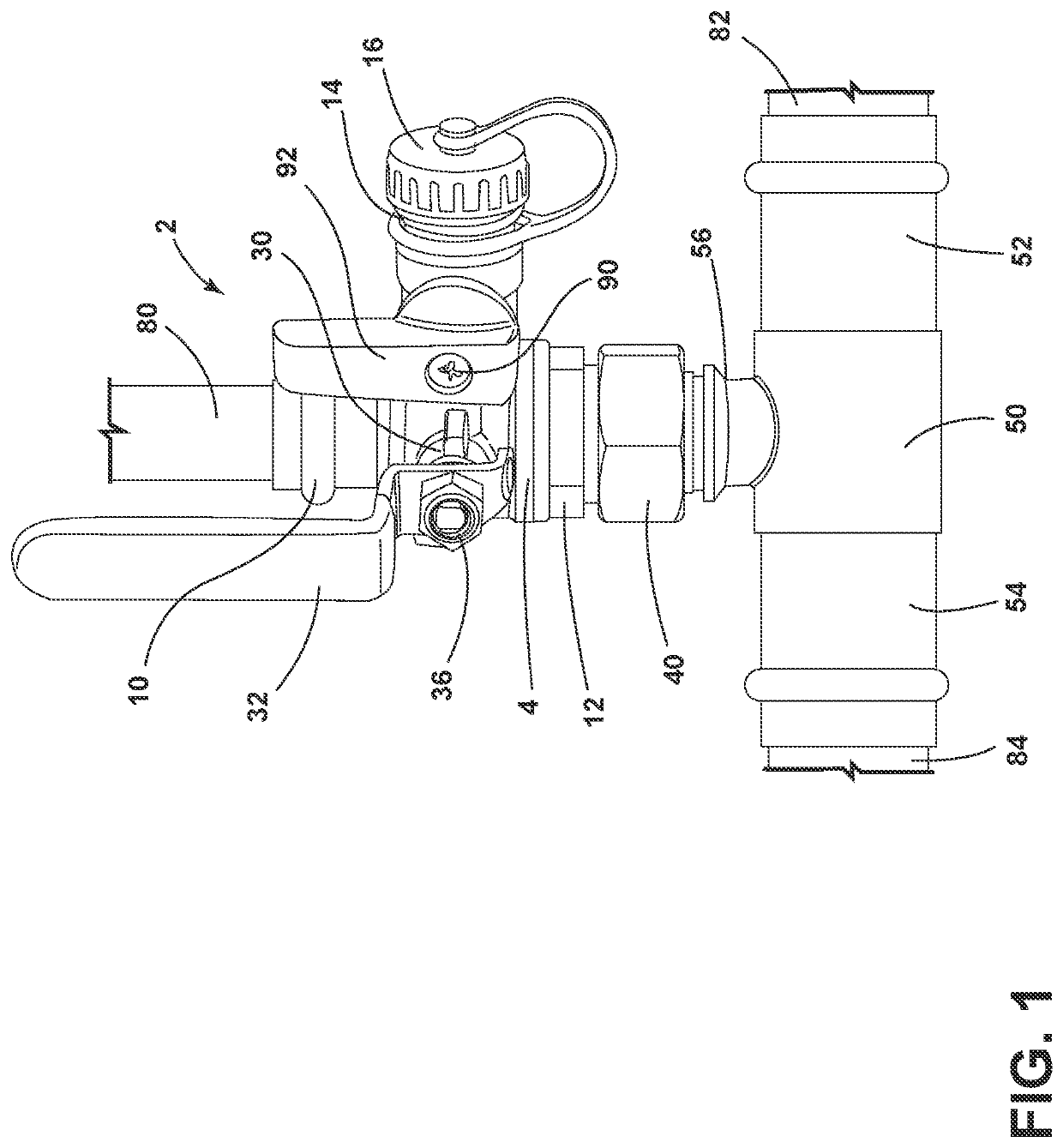
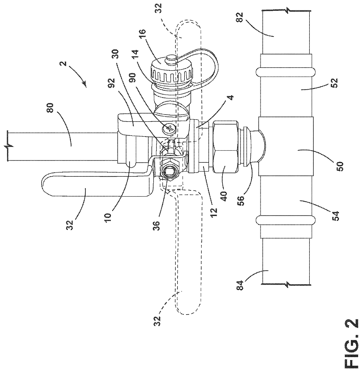
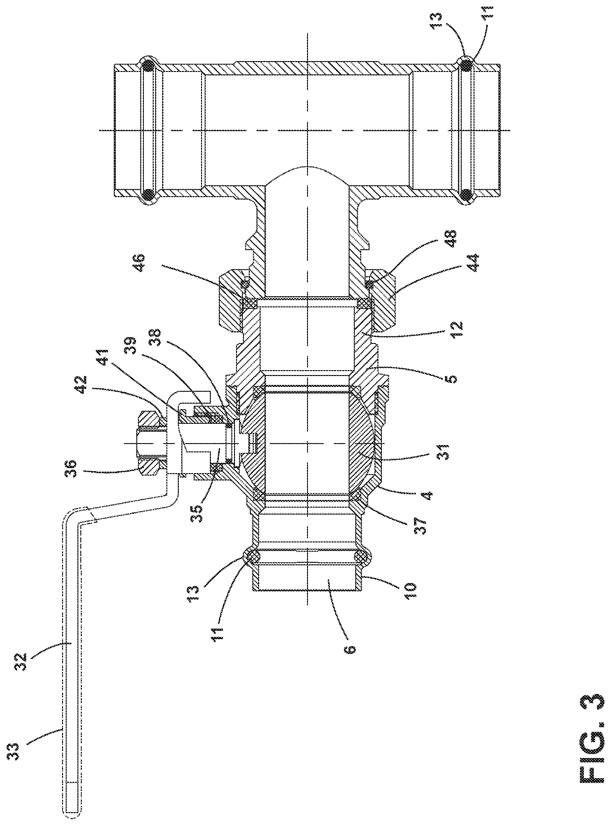
[0019]For purposes of description herein, the terms “upper,”“lower,”“right,”“left,”“rear,”“front,”“vertical,”“horizontal,” and derivatives thereof shall relate to the invention as oriented inFIGS. 1-11. However, it is to be understood that the invention may assume various alternative orientations and step sequences, except where expressly specified to the contrary. It is also to be understood that the specific devices and processes illustrated in the attached drawings, and described in the following specification, are simply exemplary embodiments of the inventive concepts defined in the appended claims. Hence, specific dimensions and other physical characteristics relating to the embodiments disclosed herein are not to be considered as limiting, unless the claims expressly state otherwise.

[0020]Detailed embodiments of the present invention are disclosed herein, however, it is to be understood that the disclosed embodiments are merely exemplary of the invention, which may be embodied...


PUM


Abstract

A tee union ball drain valve member utilizes a first valve member and a second valve member. The first valve member is positioned at the intersection of the third passageway of the valve body and the drain path. The second valve member is located in the drain path. The valve body is coupled to a tee union. The first valve member and second valve member permit draining of the valve body.

Description

BACKGROUND OF THE INVENTION[0001]The present invention relates to a tee union ball drain valve. Valves incorporating drains are well known and can be used to drain all or part of the plumbing components near the valve. Drain valves can be used in a variety of plumbing applications including, but not limited to, hydronic heating and potable plumbing systems to build header / branch assemblies that allow for quick assembly and isolation / disconnection / draining / purging / filling capabilities of the branch line by combining several fitting and valve connections. Typically, the drain valves that were incorporated above a tee union permitted draining either above or below the valve by a drain segment that was positioned, as a separate component, above or below the drain valve. A number of components are typically necessary to couple a drain, a valve, and a tee union together to piping leading to and from the valve. This typically includes at least one segment of piping in between the drain, va...

Claims


Application Information

Patent Timeline
IPC IPC(8): F16K11/087F16K27/06F16K5/06
CPCF16K11/0873F16K5/0605F16K27/065F16K27/067
Inventor MASON, CHRISTOPHER W.
Owner NIBCO INC
Why Eureka
Eureka Blog
Learn More