Vehicular heat management system

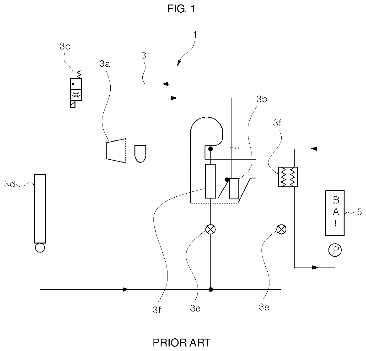
a heat management system and heat exchanger technology, applied in the direction of battery/fuel cell control arrangement, lighting and heating apparatus, transportation and packaging, etc., can solve the problems of significant reduction of the cooling performance of the low-pressure side heat exchanger b>3/b>i>f /i>, increase of refrigerant pressure loss, etc., to achieve optimal cooling performance and improve cooling/heating performance.

Pending Publication Date: 2022-06-09
HANON SYST
View PDF0 Cites 1 Cited by
  • Summary
  • Abstract
  • Description
  • Claims
  • Application Information

AI Technical Summary

Benefits of technology

[0021]In addition, since the flow rates of the refrigerant introduced into the respective heat exchangers can be independently controlled, it is possible to introduce the refrigerant into the respective heat exchangers at optimum flow rates.
[0022]Moreover, since the refrigerant can be introduced into the respective heat exchangers at optimum flow rates, it is possible to optimally control the respective low-pressure side heat exchangers. As a result, the respective low-pressure side heat exchangers can exhibit optimal cooling performance, thereby significantly improving the cooling / heating performance.

Problems solved by technology

Such a series connection structure has a disadvantage in that the refrigerant pressure loss increases.
This leads to a problem that the cooling performance of the heat exchangers 3d and 3f is significantly reduced.
This leads to a problem that the cooling performance of the low-pressure side heat exchangers 3f is lowered.
In addition, since the low-pressure side heat exchangers 3f have a structure in which the refrigerant that has passed through the upstream side outdoor heat exchanger 3d is introduced into the low-pressure side heat exchangers 3f, there is a disadvantage that the flow rate of the introduced refrigerant is inevitably limited due to the upstream side outdoor heat exchanger 3d.
Because of this disadvantage, there is a problem that the refrigerant cannot be introduced into the respective low-pressure side heat exchangers 3f at optimal flow rates suitable for the heat capacities possessed by the respective low-pressure side heat exchangers 3f.
This leads to a drawback that the cooling performance of the respective low-pressure side heat exchangers 3f is lowered.

Method used


Image

  • Vehicular heat management system
  • Vehicular heat management system
  • Vehicular heat management system

Examples


first embodiment

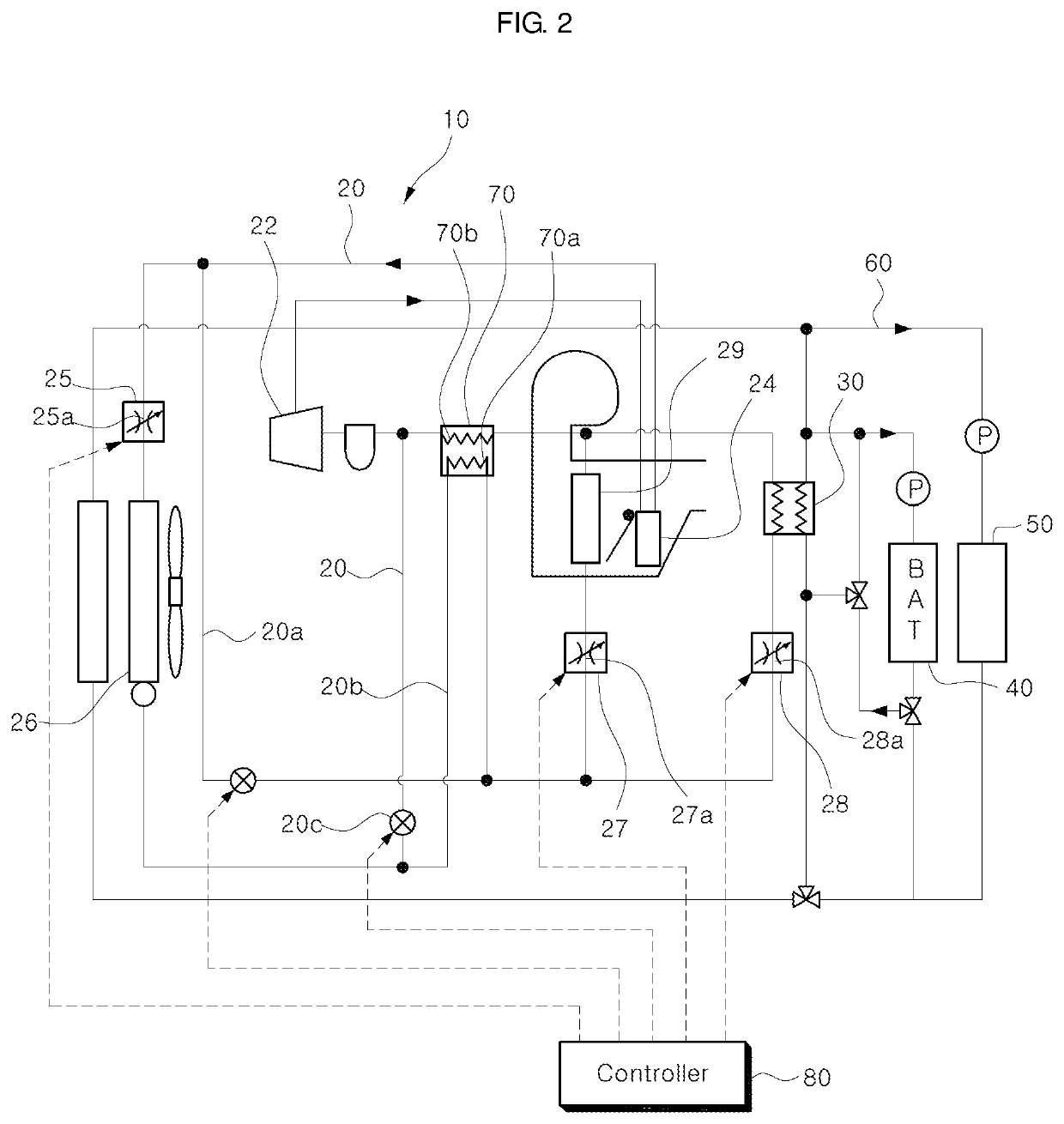
[0040]Prior to describing the features of the vehicular heat management system according to the present invention, the general configurations of the vehicular heat management system will be briefly described with reference to FIG. 2.

[0041]The vehicular heat management system includes an air conditioner 10 for cooling and heating air conditioning regions of a vehicle. The air conditioner 10 is of a heat pump type and includes a refrigerant circulation line 20.

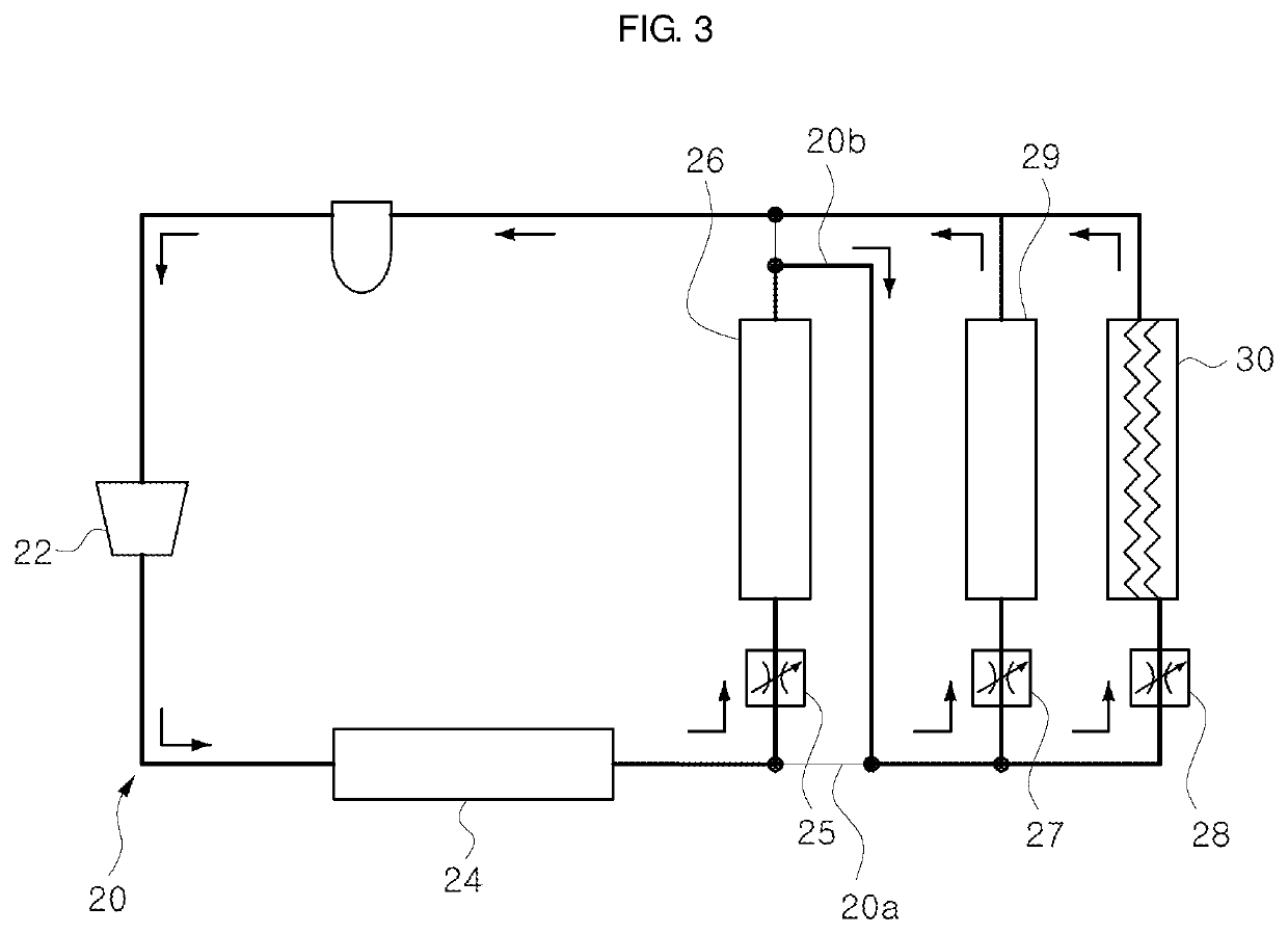
[0042]The refrigerant circulation line 20 includes a compressor 22, a high-pressure side heat exchanger 24, a heat pump mode expansion valve 25, an outdoor heat exchanger 26, a plurality of air conditioning mode expansion valves 27 and 28, and low-pressure side heat exchangers 29 and 30 (hereinafter referred to as “first low-pressure side heat exchanger 29” and “second low-pressure side heat exchanger 30”) installed on the downstream side of the air conditioning mode expansion valves 27 and 28, respectively.

[0043]The refrigerant...

second embodiment

[0100]FIG. 12 is a diagram showing a vehicular heat management system according to a second embodiment of the present invention. The vehicular heat management system according to the second embodiment has the same main configuration as that of the vehicular heat management system according to the first embodiment.

[0101]As in the first embodiment, depending on the mode state of the air conditioner 10, the outdoor heat exchanger 26 and the first and second low-pressure side heat exchangers 29 and 30 are connected in series or in parallel, whereby the outdoor heat exchanger 26 and the first and second low-pressure side heat exchangers 29 and 30 are operated in association with each other or independently of each other.

[0102]However, in the vehicular heat management system according to the second embodiment, the controller 80 variably controls the opening degrees of the variable expansion valves 25, 27 and 28 depending on the cooling / heating load and the overheating degree.

[0103]Specifi...

third embodiment

[0105]A vehicular heat management system according to a third embodiment of the present invention and an operation example thereof are shown in FIGS. 13 to 16.

[0106]Referring first to FIG. 13, the vehicular heat management system according to the third embodiment has the same main configuration as that of the vehicular heat management system according to the first embodiment.

[0107]As in the first embodiment, depending on the mode state of the air conditioner 10, the outdoor heat exchanger 26 and the first and second low-pressure side heat exchangers 29 and 30 are connected in series or in parallel, whereby the outdoor heat exchanger 26 and the first and second low-pressure side heat exchangers 29 and 30 are operated in association with each other or independently of each other.

[0108]However, in the vehicular heat management system according to the third embodiment, the heat generated in the high-pressure side heat exchanger 24 of the air conditioner 10 is transferred in a water-cool...


PUM


Abstract

A vehicular heat management system is provided with a heat pump type refrigerant circulation line that cools and heats specific air conditioning regions by generating a hot air or a cold air depending on a flow direction of a refrigerant. The system includes a compressor configured to suck, compress and discharge the refrigerant, a high-pressure side heat exchanger configured to dissipate heat of the refrigerant discharged from the compressor, an outdoor heat exchanger configured to allow the refrigerant to exchange heat with an air outside the vehicle, an expansion valve configured to depressurize the refrigerant flowing out of the high-pressure side heat exchanger or the outdoor heat exchanger, and one or more low-pressure side heat exchangers configured to evaporate the depressurized refrigerant. The outdoor heat exchanger and the low-pressure side heat exchangers are connected in series or in parallel depending on an air conditioning mode.

Description

TECHNICAL FIELD[0001]The present invention relates to a vehicular heat management system and, more particularly, to a vehicular heat management system capable of controlling the refrigerant flow between low-pressure side heat exchangers in series or in parallel according to the air conditioning mode state, independently controlling the flow rates of the refrigerant introduced into the respective low-pressure side heat exchangers according to the air conditioning mode state, and introducing the refrigerant into the respective low-pressure side heat exchangers at optimal flow rates suitable for the respective low-pressure side heat exchangers.BACKGROUND ART[0002]Examples of an eco-friendly vehicle include an electric vehicle, a hybrid vehicle and a fuel cell vehicle (hereinafter collectively referred to as a “vehicle”).[0003]As shown in FIG. 1, such a vehicle is equipped with an air conditioner 1 for cooling and heating air conditioning regions.[0004]The air conditioner 1 is of a heat...

Claims


Application Information

Patent Timeline
Patent Type & Authority Applications(United States)
IPC IPC(8): B60H1/00B60H1/22
CPCB60H1/00385B60H1/00278B60H1/00899B60H1/00485B60H1/00885B60L58/26B60H1/2221B60H2001/00949B60H2001/00942B60H2001/00961B60H1/2218F25B41/20F25B41/24B60L2240/545F25B5/04F25B5/02F25B49/02F25B2600/2519F25B40/00F25B47/022B60H2001/00307B60H1/00921B60H2001/00928B60H1/32281
Inventor LEE, JUN MINKIM, YONG SIKKIM, CHUL HEELEE, BYEONG HAJUNG, JAE OLEE, JIN JAEKIM, DOO HOONAN, KYUNG JUHAN, JOONG MAN
Owner HANON SYST
Why Eureka
Try Eureka