System for shielding a tone ring in a vehicle axle

a technology for shielding and tone rings, which is applied in the direction of brake systems, instruments, braking components, etc., can solve the problems of adding cost and complexity to the manufacture and service of the axle assembly, damage to the tone rings, and easy to be struck by the axle shaft. , to achieve the effect of adding cost and complexity, effective system for shielding the tone rings

Active Publication Date: 2022-06-09
DANA HEAVY VEHICLE SYSTEMS GROUP LLC
View PDF3 Cites 0 Cited by
  • Summary
  • Abstract
  • Description
  • Claims
  • Application Information

AI Technical Summary

Benefits of technology

The patent text describes a system for protecting a tone ring in a vehicle's anti-lock braking system from damage caused by an axle shaft during installation. The system involves a snap-in plastic shield that is easily attached to the tone ring without using tools. The shield is designed to prevent metal-to-metal contact between the axle shaft and the tone ring, reducing the likelihood of damage to the ring. The shield also acts as a guide for centering the axle shaft during installation. Overall, the system improves the manufacture and service of the axle assembly while safeguarding the quality and functionality of the anti-lock braking system.

Problems solved by technology

A tone ring assembly of a vehicle is often susceptible to being struck by an axle shaft during installation.
While installing the shaft through the tone ring, the shaft may come in contact with the bare tone ring, which can cause damages to the tone ring.
This may add cost and complexity to the manufacture and service of the axle assembly.
However, the inventors herein have identified potential problems in the systems such as those noted above.
As one example, the systems described by Dobbs et al. and Crepas do not shield the tone ring from an axle shaft, and therefore the tone ring may not be able to withstand reasonable axle shaft impact forces.
Additionally, the retainer used in the system of Dobbs et al. is only partially disposed around a portion of the tone ring, leaving the rest of the portion of tone ring exposed that may be vulnerable to being struck by an axle shaft during installation.

Method used


Image

  • System for shielding a tone ring in a vehicle axle
  • System for shielding a tone ring in a vehicle axle
  • System for shielding a tone ring in a vehicle axle

Examples


Embodiment Construction

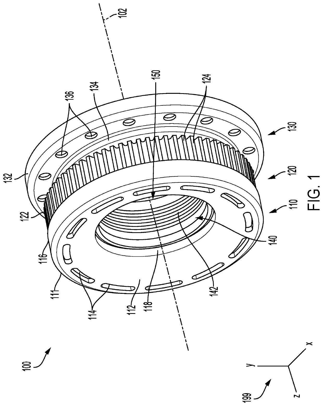
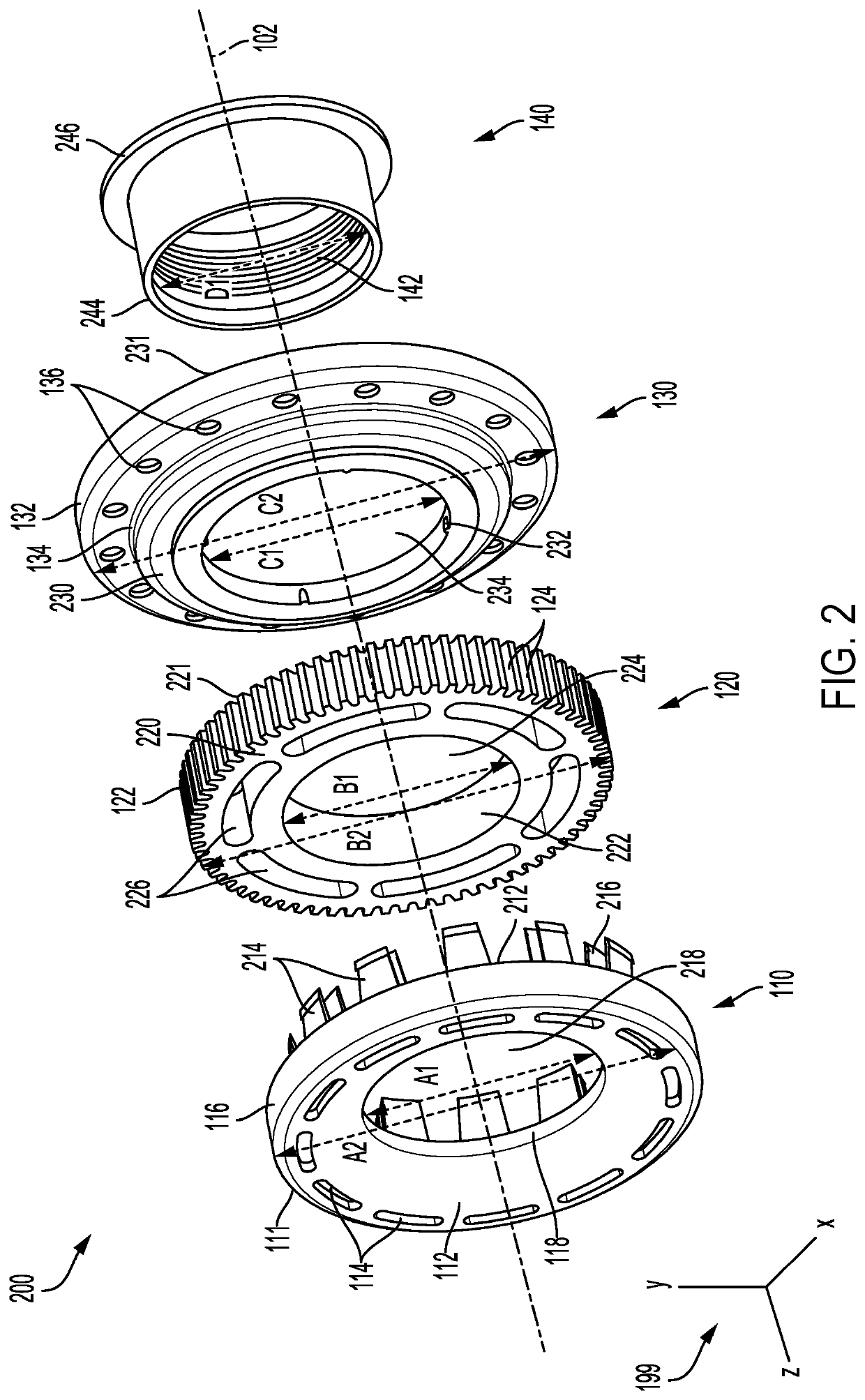
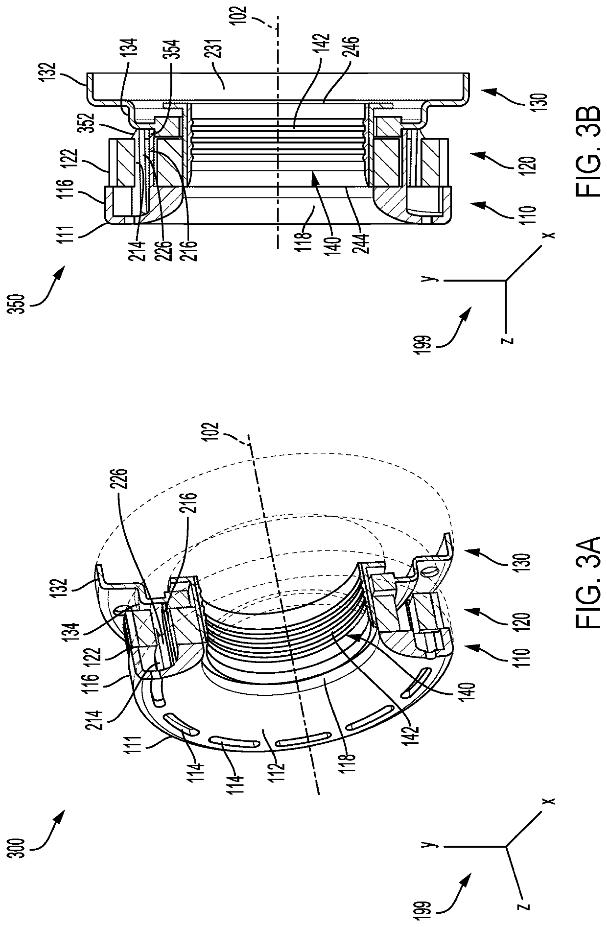
[0017]The following description relates to a shielding system for an axle tone ring that is configured to protect the tone ring from interfacing with an axle shaft. An exemplary tone ring assembly, according to the present disclosure, is shown in an assembled form in FIG. 1. FIG. 2 illustrates an exploded view of the tone ring assembly showing a plurality of component parts of the assembly. An engagement of four different component parts constitutes the tone ring assembly, according to the present disclosure. Cross-sectional views of the assembled tone ring assembly system are provided in FIGS. 3A-3B, showing the internal features of the assembly. FIGS. 4 and 5 illustrate a close-up bottom perspective view and a close-up top perspective view of the shield of the tone ring assembly, respectively, highlighting a variety of features in accordance with an example of the present disclosure.

[0018]FIG. 1 shows a perspective view of an exemplary tone ring assembly 100 in a fully assembled f...


PUM


Abstract

A system is provided for shielding a tone ring assembly in automotive vehicles. The system comprises a ring cap with a central aperture, a plurality of molding slides circularly arranged on a first side of the ring cap, a plurality of snap-fit arms and a plurality of pilot tabs positioned on a second side of the ring cap, where the plurality of pilot tabs and the plurality of snap-fit arms are arranged in concentric circles with the snap-fit arms forming an outer circle and the pilot tabs forming an inner circle, and where each pilot tab of the plurality of pilot tabs is positioned directly behind a corresponding snap-fit arm of the plurality of snap-fit arms. In one example, the system prevents metal to metal contact between a tone ring and a shaft during axle shaft installation.

Description

TECHNICAL FIELD[0001]The present disclosure relates generally to systems for protecting axle tone ring in automotive vehicles.BACKGROUND AND SUMMARY[0002]A tone ring, being a part of an anti-lock braking system of a vehicle, is a notched ring that is used in conjunction with a sensor to determine number or speed of revolutions. A tone ring assembly of a vehicle is often susceptible to being struck by an axle shaft during installation. An axle shaft is usually installed in a vehicle after the tone ring is installed on a carrier assembly. While installing the shaft through the tone ring, the shaft may come in contact with the bare tone ring, which can cause damages to the tone ring. This may add cost and complexity to the manufacture and service of the axle assembly. Therefore, an effective system for shielding the tone ring from axle shaft is highly desirable.[0003]An example unitized tone ring assembly system is shown by Dobbs et al. in US 20030085697A1. Therein, an assembly compris...

Claims


Application Information

Patent Timeline
Patent Type & Authority Applications(United States)
IPC IPC(8): G01P1/02G01P3/00
CPCG01P1/026B60T8/329G01P3/00B60T17/00B60B35/00G01P3/488B60T17/22B60T2270/10
Inventor CREPAS, ROBERT E.GRIES, AARON D.LEBER, MARK W.
Owner DANA HEAVY VEHICLE SYSTEMS GROUP LLC
Why Eureka
Try Eureka