

Suction/compression rotating mechanism, rotary compressor and rotary engine
- Summary
- Abstract
- Description
- Claims
- Application Information
AI Technical Summary
Benefits of technology
Problems solved by technology
Method used
Image

Examples
Embodiment Construction
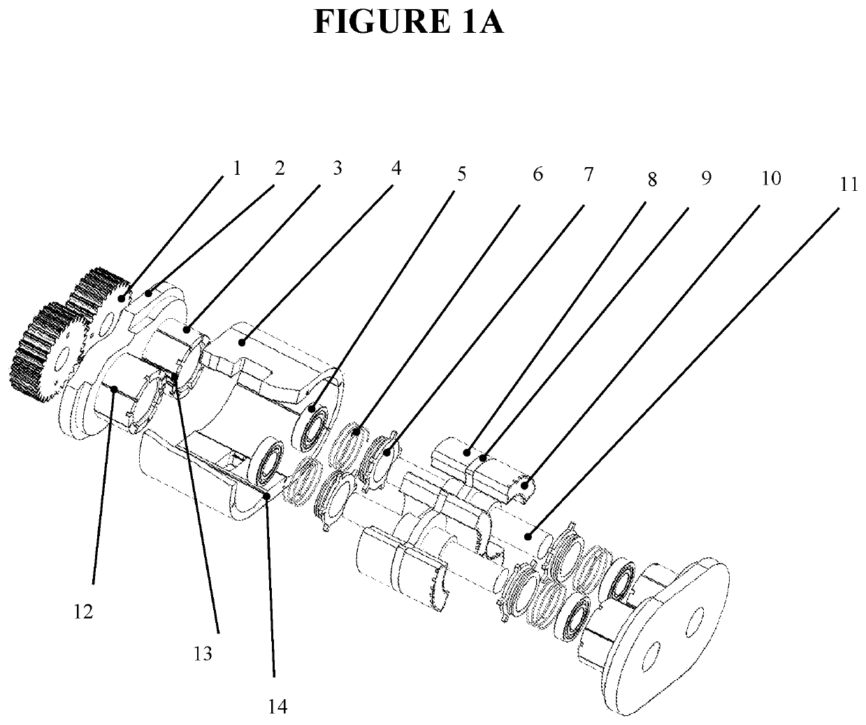
[0035]FIG. 1: Overview of the general structure and the main details of the compressor:
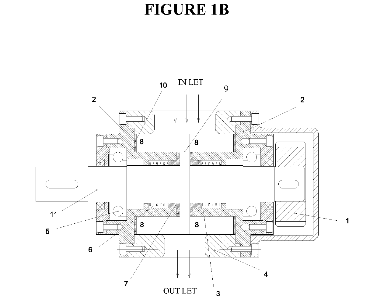
[0036]The pair of drive gears (1) is fastened on the two shafts (11), they drive the pistons to work together accordingly; The pump walls (2) and pump casing (4) are precisely assembled together thanks to the positioning brackets on the pump wall that forming the pump chamber; Ball bearings (5) are bearings that support axes, which are placed in cylinders (3) protruding from the pump wall (2); The springs (6) are also arranged in the cylinders (3) they always push the sealing rings (7) close to the side of the bearing plates (9) to seal the gap between the top face of the cylinders (3) and the side of the bearing plates (9);
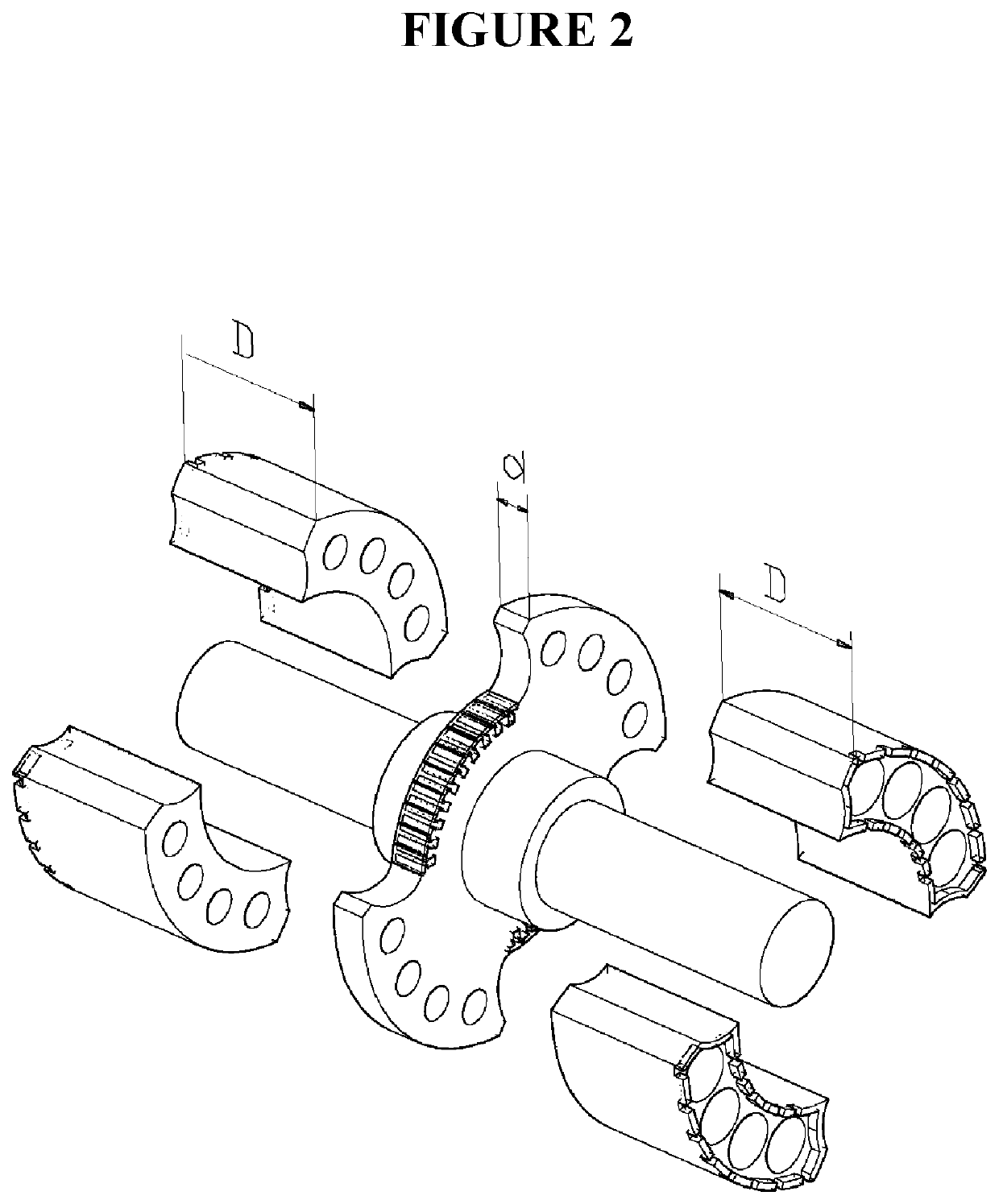
[0037]The bearing plates (9) are fastened on the shaft (11) and the piston (8); The pistons (8) are symmetrically mounted on both sides of the plates (9) and symmetrically double through the center of rotation of the axes (11), which makes the whole block around the axes (11) b...
PUM
 Abstract
Description
Claims
Application Information