Method for Controlling the Volume Flow Rate From a Nozzle

a technology of volume flow and nozzle, which is applied in the direction of coating, material granulation, pharmaceutical product form change, etc., can solve the problems of affecting the process, affecting the process, and affecting the process, so as to prevent the effect of caking on, infinite change of the volume of the device, and the effect of preventing the occurrence of undesirable agglomerates

Pending Publication Date: 2022-06-30
GLATT GMBH
View PDF0 Cites 1 Cited by
  • Summary
  • Abstract
  • Description
  • Claims
  • Application Information

AI Technical Summary

Benefits of technology

[0019]A part-section of the inlay is preferably changeable in length. On account of the length changeability of the part-section of the inlay which projects at least partly out of the inner pipe or the outer pipe of the nozzle, it is possible to change the movability of the part-section, in particular the frequency of the vibration of the part-section of the inlay and to adapt it for example to changed process conditions during the manufacturing process and / or spraying process. By way of this, one can influence the manufacturing process and / or spraying process in a direct manner by way of the vibration frequency of the inlay being adapted or adaptable to the substance to be sprayed, in particular liquid, for example a highly viscous fluid or a suspension, emulsion or the like. By way of this, one prevents deposits arising at the nozzle mouthpiece. If the nozzles, in particular their nozzle mouthpiece is monitored by sensor devices, such as for example a camera, then it is furthermore possible to change the frequency online during the running process, so that caking-on can be prevented.
[0020]Furthermore, with regard to a method of the aforementioned type, this object is achieved in that the inner pipe at least partly is designed of an elastic material and a device which comprises an inlet for fluid feed and an outlet for a fluid discharge is arranged in the annular gap between the inner pipe and the outer pipe, wherein the device has a closure position for closing the inner pipe and at least one open position, wherein in the at least one open position the substance to be sprayed can flow through at least the fluid channel, and wherein the device is designed in a manner such that the volume of the device can be changed by way of fluid feed or fluid discharge, by which means the device can be brought or is brought from the one closure position of the inner pipe into the at least one open position of the inner pipe and vice versa, wherein fluid is discharged out of the device so that its volume is reduced, for bringing the device from the one closure position of the inner pipe into the at least one open position of the inner pipe, or fluid is fed to the device so that its volume increases, for bringing the device from the at least one open position of the inner pipe into the one closure position of the inner pipe. The advantage of this embodiment of the method according to the invention is the fact that the volume flow of the substance to be sprayed can be optimally adapted to the process, in particular to the coating method in the pharmaceutics industry. Further advantageously, the volume of the device is infinitely changeable by way of the fluid feed and fluid discharge. Very particularly preferably, the volume of the device is hereby adjusted by way of the fluid feed or fluid discharge by a control device or closed-loop control device.

Problems solved by technology

These spraying processes can last for several hours.
If the droplets are too small, then there is the danger that they dry before they reach their target, and if the droplets are too large, there is the danger of undesirable agglomerates arising.
These deposits influence the symmetry and droplet size of the spray, so that effects upon the process which are not desirable, such as for example spray drying and / or local over-humidification and agglomeration occur.
Furthermore, deposits are produced by way of an unsuitable through-flow control and / or closed loop control of the volume flow of the substance to be sprayed in relation to the gas which atomises the substance to be sprayed, in other words the particles are coated with an inadequate spray quality.
The disadvantage of the aforementioned technical solutions is the fact that these self-cleaning nozzles which are mentioned in the state of the art each on the one hand have a large number of individual parts which are built together into complex nozzles which are maintenance-intensive, by which means the cited technical solutions are expensive in production and maintenance, and on the other hand there are no suitable methods to spray the substance to be sprayed, in a manner such that no or at least less deposits form on the nozzle mouth and despite this permits the volume flows of the substance to be sprayed and of the gas to be adjusted in a precise manner.

Method used


Image

  • Method for Controlling the Volume Flow Rate From a Nozzle
  • Method for Controlling the Volume Flow Rate From a Nozzle
  • Method for Controlling the Volume Flow Rate From a Nozzle

Examples


first embodiment

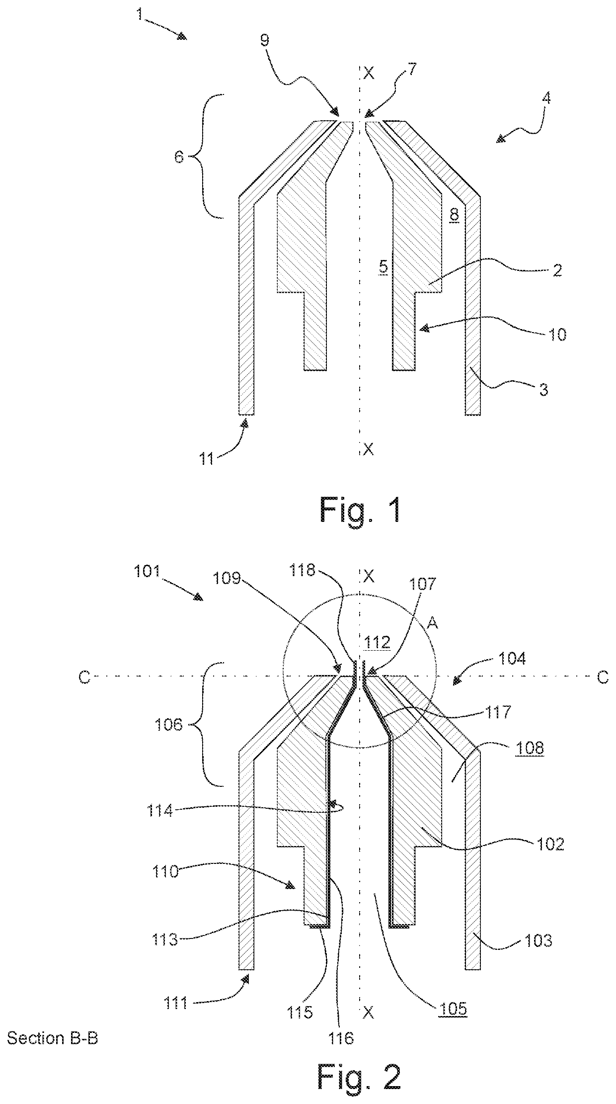
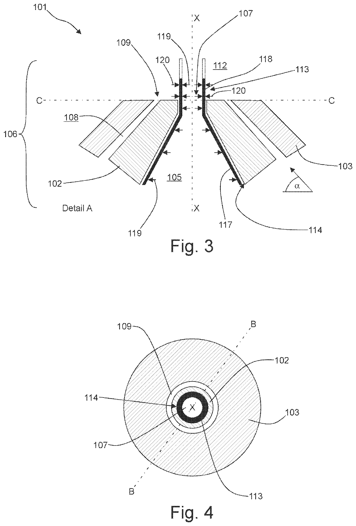
[0042]FIG. 2 shows a section B-B according to FIG. 4 through preferred nozzle 101. The preferred nozzle 101, as already represented in FIG. 1, comprises a nozzle body 104 which has an inner pipe 102 and an outer pipe 103. The inner pipe 102 and the outer pipe 103 are arranged coaxially to an axis X-X. The inner pipe 102 comprises a fluid channel 105 for feeding the substance to be sprayed, preferably a liquid, very particularly preferably a dispersion, suspension, or emulsion. This runs out into an exit opening 107 of the inner pipe 102 in the region of the nozzle mouthpiece 106. In the region which is away from the exit opening 107 of the inner pipe 102, the inner pipe 102 comprises a connection location 110 for a feed conduit for the substance to be sprayed, said feed conduit not being represented. The outer pipe 103 is arranged in a manner distanced to the inner pipe 102, by which means an annular gap 108 for feeding the gas, in particular atomisation gas forms. The annular gap 1...

second embodiment

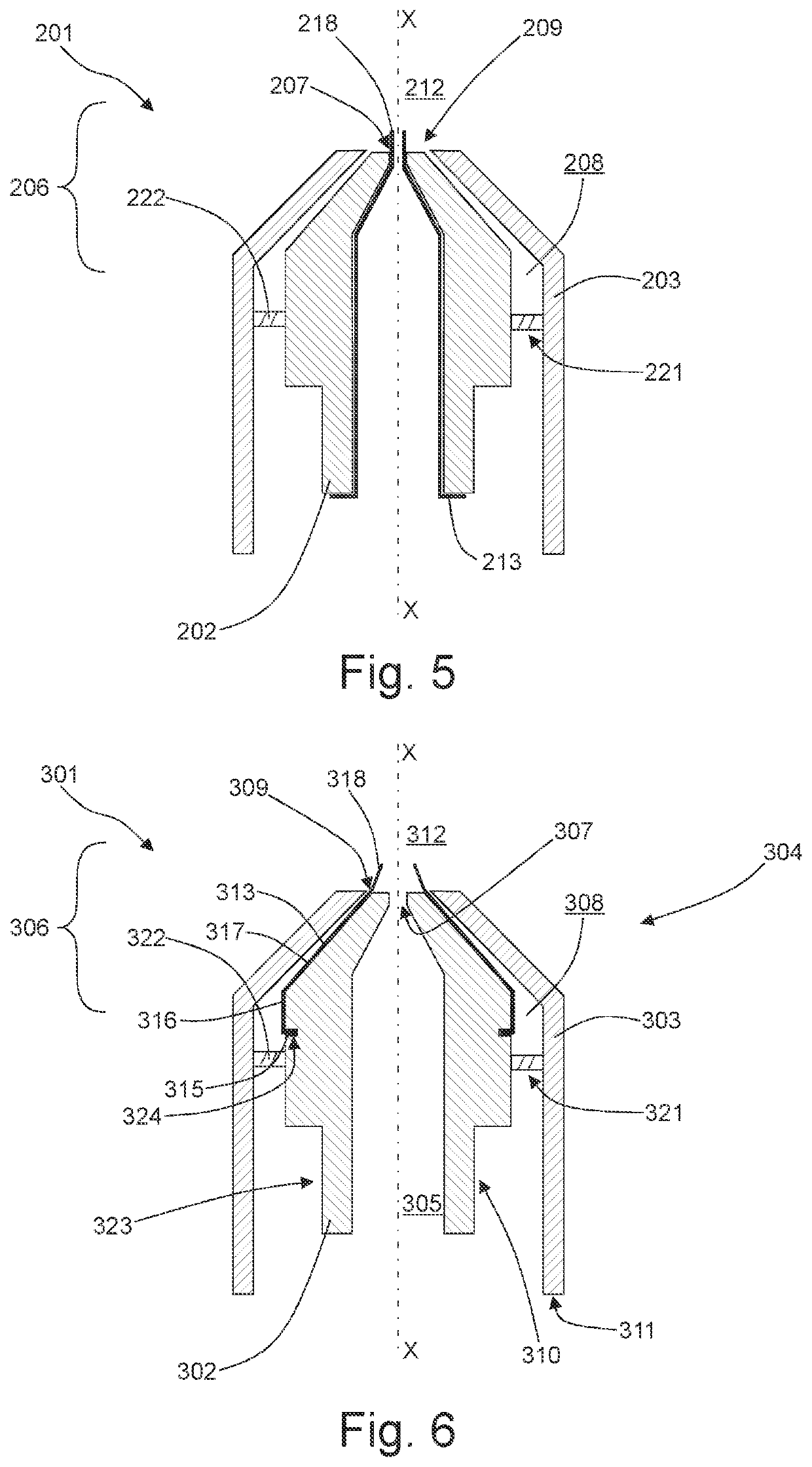
[0052]A section through a preferred nozzle 201 with an optional attachment part 220 in the annular gap 208 in the form of a swirl plate for the guidance of the gas is represented in FIG. 5.

[0053]The preferred nozzle 201 according to the second embodiment in its basic construction corresponds to the first embodiment of the preferred nozzle 101 which is shown in FIGS. 2 to 4. The difference between the two embodiments is the fact that the preferred nozzle 201 in contrast to the nozzle 101 comprises an optional attachment part 221 which is designed in the form of a swirl plate for leading the gas. In the present second embodiment of the preferred nozzle 201, the attachment part 221 comprises openings 222 which are at an angle to the gas, in particular atomisation gas, which flows parallel to the outer pipe 203. By way of this, the gas which flows in the annular gap 208 undergoes a swirling about the axis X-X. The onflow and the movement behaviour and thus also the vibration frequency o...

third embodiment

[0055]FIG. 6 shows a section through a further, third embodiment of a preferred nozzle 301 with an optional attachment part 321 in the annular gap 308 in the form of a swirl plate for leading gas. The preferred nozzle 301 comprises a nozzle body 304 which has an inner pipe 302 and an outer pipe 303, wherein the inner pipe 302 and the outer pipe 303 are arranged coaxially to an axis X-X. The inner pipe 302 comprises a fluid channel 305 which is designed for feeding the substance to be sprayed. This channel opens out into an exit opening 307 of the inner pipe 302 in the region of the nozzle mouthpiece 306. In the region which is away from the exit opening 307 of the inner pipe 302, the inner pipe 302 comprises a coupling location 310 which for a feed conduit for the substance to be sprayed, preferably a liquid, very particularly preferably a dispersion, emulsion, or suspension, said feed conduit not being shown.

[0056]The outer pipe 303 is arranged in a manner distanced to the inner pi...


PUM

PropertyMeasurementUnit
frequencyaaaaaaaaaa
frequencyaaaaaaaaaa
frequencyaaaaaaaaaa

Abstract

Methods for controlling or regulating the volume flow rate of a substance to be sprayed and/or a gas from a nozzle suitable for spraying substances, particularly dispersions, emulsions or suspensions, wherein the nozzle has a nozzle body comprising a nozzle mouthpiece, wherein the nozzle body has an inner pipe, which is connected to a supply for the substance to be sprayed and has an inner wall and a discharge port, and an outer pipe, which is spaced from the inner pipe, is connected to a supply for a gas and has a discharge port, and the discharge port of the inner pipe and the discharge port of the outer pipe are arranged in the region of the nozzle mouthpiece.

Description

CROSS-REFERENCE TO RELATED APPLICATIONS[0001]This application is the United States national phase of International Application No. PCT / EP2020 / 056529 filed Mar. 11, 2020, and claims priority to German Patent Application No. 10 2019 205 743.8 filed Apr. 18, 2019, the disclosures of which are hereby incorporated by reference in their entirety.BACKGROUNDField[0002]The invention relates to a method for the control or closed-loop control of the volume flow of a substance to be sprayed and / or of a gas, of a nozzle which is suitable for spraying substances, in particular dispersions, emulsions, or suspensions, wherein the nozzle comprises a nozzle body which has a nozzle mouthpiece, wherein the nozzle body comprises an inner pipe, said inner pipe being connected to a feed for the substance to be sprayed and comprising an inner wall and an exit opening, and an outer pipe, said outer pipe being distanced to the inner pipe, being connected to a feed for a gas and comprising an exit opening, an...

Claims


Application Information

Patent Timeline
Patent Type & Authority Applications(United States)
IPC IPC(8): A61J3/00B01J2/00B01J2/02B05B1/08B05B1/32B05B12/08B05B15/50B05B15/52B05B3/16B05B7/06B05B7/10B05B7/12
CPCA61J3/005B01J2/006B01J2/02B05B1/086B05B1/323B05B12/085B05B7/1245B05B15/52B05B3/16B05B7/066B05B7/10B05B7/1281B05B15/50
Inventor NOWAK, REINHARDSTEINKE, LARS
Owner GLATT GMBH
Why Eureka
Try Eureka