
Gate driving circuit and electroluminescent display device using the same

a driving circuit and electroluminescent display technology, applied in static storage, digital storage, instruments, etc., can solve the problems of complicated configuration of gate driving circuits, increased bezels, and increased driving power consumption

Active Publication Date: 2022-06-30
LG DISPLAY CO LTD
View PDF4 Cites 2 Cited by
  • Summary
  • Abstract
  • Description
  • Claims
  • Application Information

AI Technical Summary

Benefits of technology

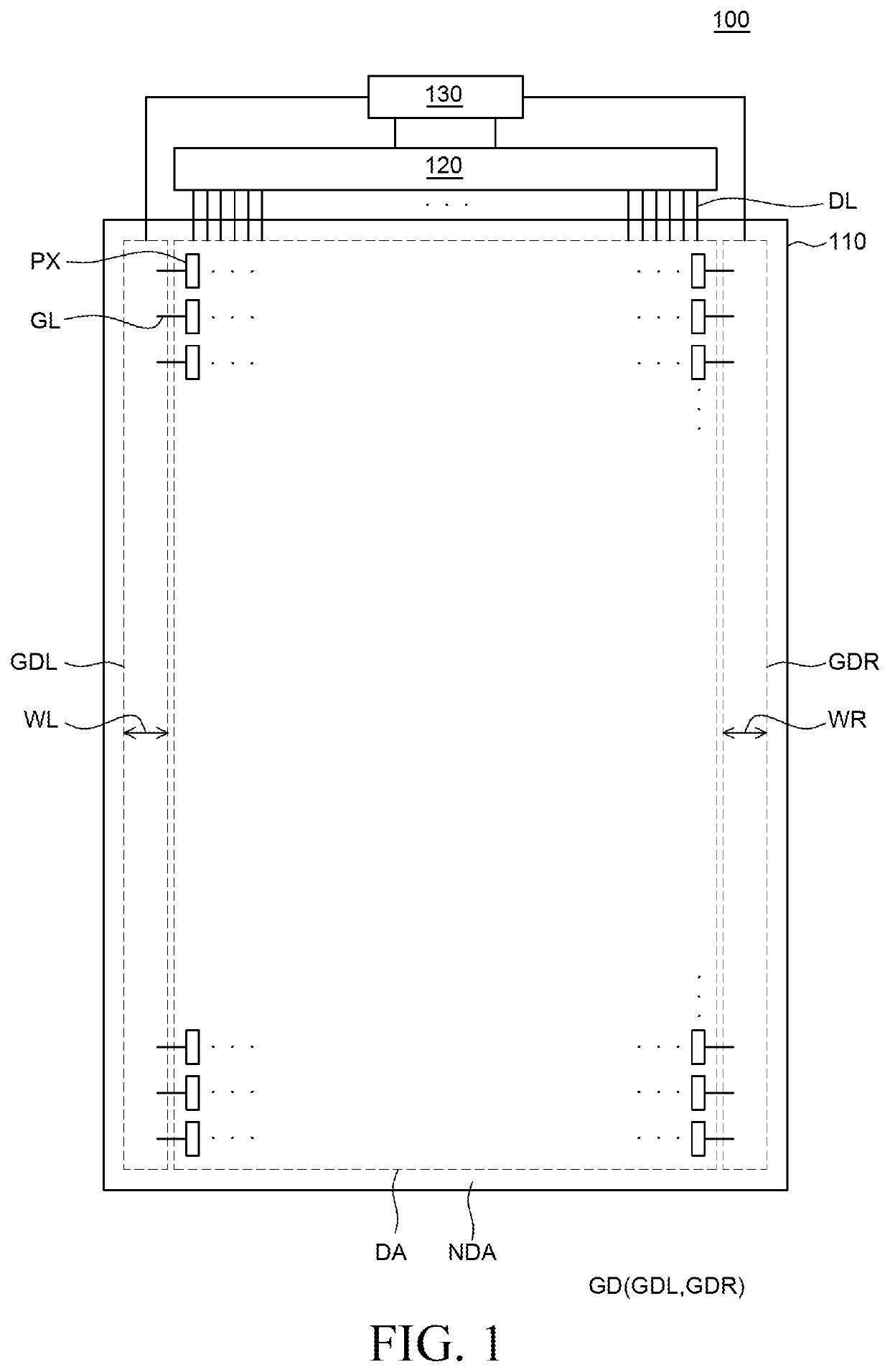
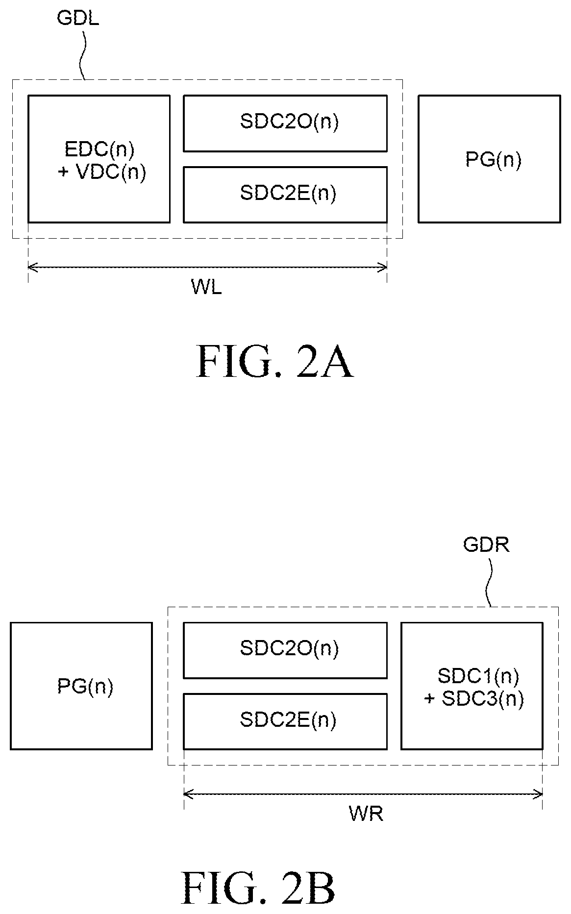
This patent describes a way to simplify the circuitry and reduce the area of a display panel by integrating a gate driving circuit into the non-display area of the panel. The circuitry uses a combination of thin film transistors to generate gate signals that are sent to the display area through gate lines. The process of generating the gate signals using a combination of circuits can be complicated and takes up space. By using a Q node or Q′ node, or an emission signal inverter, the circuitry can be simplified and the bezel of the display can be reduced. This simplification process is especially useful for electroluminescent display devices.

Problems solved by technology

Further, since the electroluminescent display device includes a separate circuit for applying on bias stress in the gate driving circuit, a bezel increases and driving power consumption increases.
Accordingly, as the number of gate signals to be supplied to the pixel array increases, a configuration of the gate driving circuits is complicated and has a large area, which may increase a bezel of the display panel.
Also, as described above, in order to apply on bias stress to the pixel array, the configuration of the gate driving circuit may be complicated and the bezel may be increased.

Method used


Image

  • Gate driving circuit and electroluminescent display device using the same
  • Gate driving circuit and electroluminescent display device using the same
  • Gate driving circuit and electroluminescent display device using the same

Examples


Embodiment Construction

[0030]Advantages and characteristics of the present disclosure and a method of achieving the advantages and characteristics will be clear by referring to embodiments described below in detail together with the accompanying drawings. However, the present disclosure is not limited to the embodiments disclosed herein but will be implemented in various forms. The embodiments are provided by way of example only so that those skilled in the art can fully understand the disclosures of the present disclosure and the scope of the present disclosure.

[0031]The shapes, sizes, ratios, angles, numbers, and the like illustrated in the accompanying drawings for describing the embodiments of the present disclosure are merely examples, and the present disclosure is not limited thereto. Like reference numerals generally denote like elements throughout the specification. Further, in the following description of the present disclosure, a detailed explanation of known related technologies may be omitted ...


PUM

PropertyMeasurementUnit
reversal voltageaaaaaaaaaa
voltageaaaaaaaaaa
phaseaaaaaaaaaa

Abstract

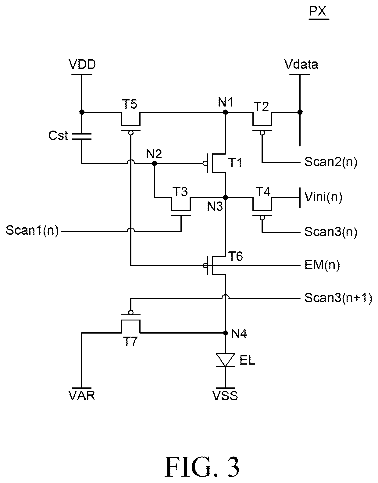
Provided is an electroluminescent display device. The electroluminescent display device includes a pixel circuit implemented with a plurality of transistors, and a gate driving circuit that provides a scan signal, an initialization signal, and an emission signal to the pixel circuit. The gate driving circuit includes a scan signal generating circuit that provides the scan signal to a gate electrode of at least one of the plurality of transistors, an initialization signal generating circuit that provides the initialization signal to a source electrode or a drain electrode of at least one of the plurality of transistors, and the emission signal generating circuit that provides an emission signal to the gate electrode of at least one of the plurality of transistors. The initialization signal generating circuit receives an output signal of the scan signal generating circuit and an output signal of the emission signal generating circuit.

Description

CROSS-REFERENCE TO RELATED APPLICATIONS[0001]This application claims the benefit of and priority to Korean Patent Application No. 10-2020-0181933 filed on Dec. 23, 2020 in the Republic of Korea, the entire contents of which are hereby expressly incorporated by reference into the present application.BACKGROUNDTechnical Field[0002]The present disclosure relates to a simplified gate driving circuit and an electroluminescence display device using the same.Discussion of the Related Art[0003]In accordance with the development of information technology, the market for display devices that are connection media between users and information, is growing. Accordingly, the use of various types of display devices such as an electroluminescent display device, a liquid crystal display device, an organic light emitting display device, and a quantum dot display device is increasing.[0004]Among them, the electroluminescent display device has advantages in terms of a fast response speed, high luminous...

Claims


Application Information

Patent Timeline
Patent Type & Authority Applications(United States)
IPC IPC(8): G09G3/30
CPCG09G3/30G09G2310/0267G09G2320/0233G09G2300/0842G09G2320/0214G09G2310/08G09G3/2074G09G3/3266G09G3/3291G09G3/3241G09G2310/0251G09G2300/0895G09G2310/0286G11C19/28G09G3/3275
Inventor KIM, MINSUKIM, SEHWAN
Owner LG DISPLAY CO LTD
Learn More