Electronic arrangement for an aircraft and method for providing such an electronic arrangement

a technology for aircraft and electronic arrangement, applied in the direction of fuselage, polarised antenna unit combination, transportation and packaging, etc., can solve the problems of increasing fuel consumption during operation, high level of calculation and certification complexity, maintenance operations and subsequent replacement,

Pending Publication Date: 2022-07-07
AIRBUS OPERATIONS GMBH
View PDF1 Cites 1 Cited by
  • Summary
  • Abstract
  • Description
  • Claims
  • Application Information

AI Technical Summary

Problems solved by technology

On the one hand, the air resistance of the aircraft is thereby increased, which increases the fuel consumption during operation, and, on the other hand, for each aircraft type, for each electronic device and each positioning of the electronic device, the aerodynamic pressure and suction forces which occur on the outer faces of the electronic device and which are also referred to as aerodynamic loads must

Method used


Image

  • Electronic arrangement for an aircraft and method for providing such an electronic arrangement
  • Electronic arrangement for an aircraft and method for providing such an electronic arrangement
  • Electronic arrangement for an aircraft and method for providing such an electronic arrangement

Examples


first embodiment

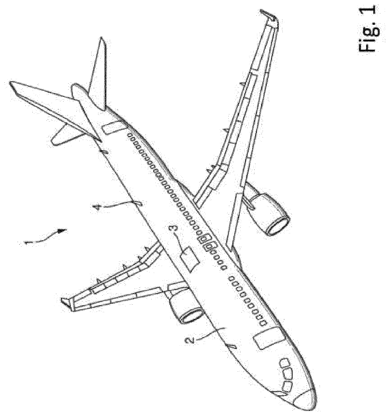
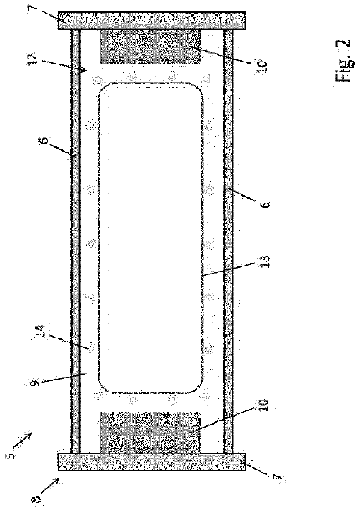
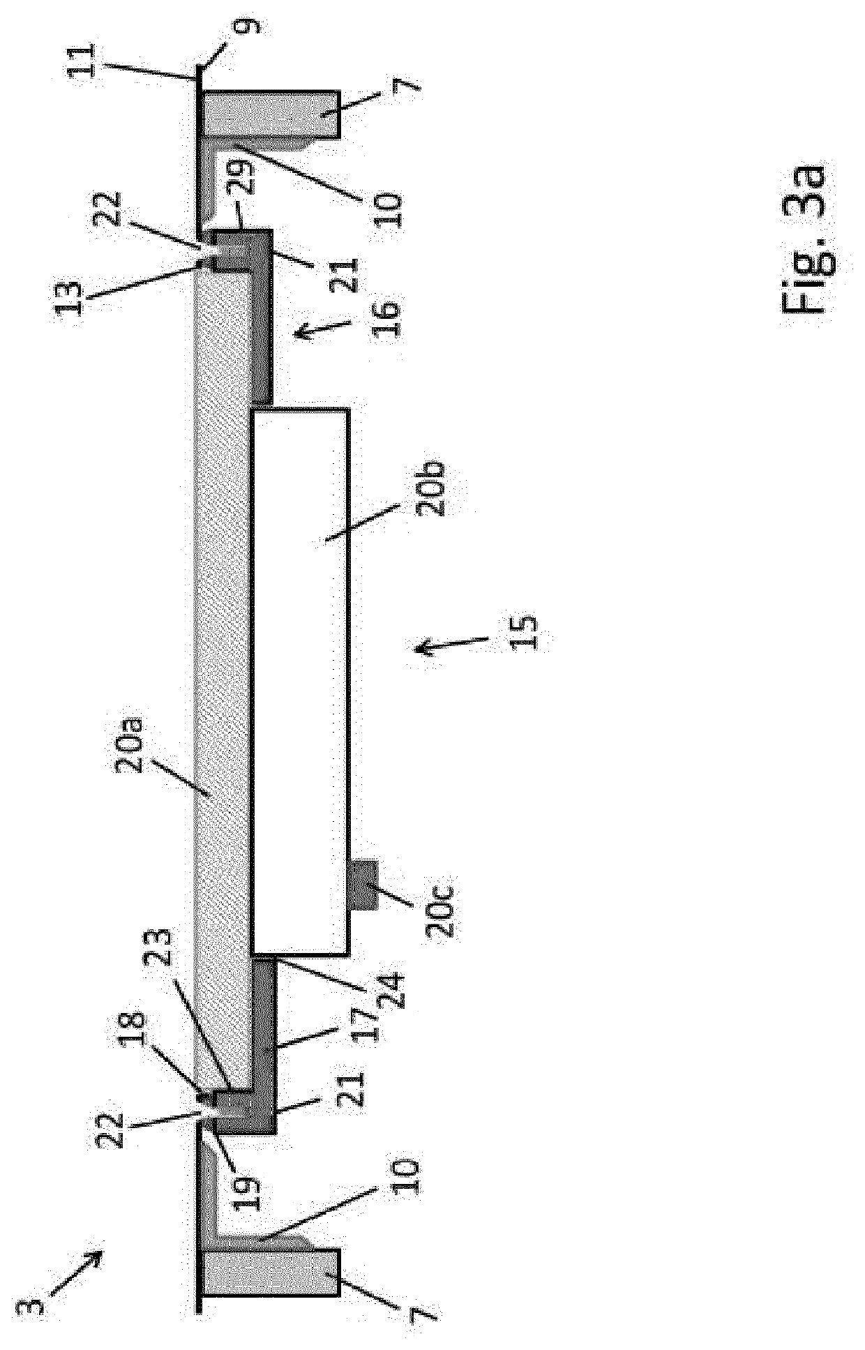
[0038]FIG. 2 is a schematic plan view of a structural portion 5 of the aircraft 1 which—as set out above—may, for example, be a fuselage structural portion. The structural portion 5 has two longitudinal reinforcement elements 6 and two transverse reinforcement elements 7 which are connected to each other and which together form a reinforcement arrangement 8 of longitudinal and transverse reinforcement elements 6, 7. The longitudinal reinforcement elements 6 extend in the state installed in the fuselage 2 in the longitudinal direction of the fuselage 2 and the transverse reinforcement elements 7 extend in the circumferential direction of the fuselage 2 perpendicularly to the longitudinal reinforcement elements 6. On the other hand, the structural portion 5 has an outer skin 9 which is arranged at one side of the reinforcement arrangement 8 and which is secured thereto. As can be seen inter alia in FIG. 3a, which is a schematic side view of an antenna arrangement 3 according to the in...

second embodiment

[0042]FIG. 4 shows the antenna arrangement 3. This differs from the embodiment shown in FIGS. 3a to 3c substantially only in that the frame 16 is not constructed in a trough-like manner and has no receiving space and in that, in place of the antenna element 20a, a leaf antenna element 26 which projects outwardly from the outer face 11 of the outer skin 9 is provided.

third embodiment

[0043]FIG. 5 shows the antenna arrangement 3. In this embodiment, the structural portion 5 has three longitudinal reinforcement elements 7 and two adjacent skin panels 12, wherein in each of these skin panels 12 an opening 13 and a structural element 15 are provided. The one structural element 15 (on the left in FIG. 5) has substantially the same structure as the structural element 15 of FIG. 3a. In place of the antenna element 20a, however, an antenna element 27 which shares this structural element 15 with the other structural element 15 (on the right in FIG. 5) and which is secured to each of the frames 16 of the two structural elements 15 is provided. This antenna element 27 therefore extends over both skin panels 12 and can consequently be constructed to be larger than the antenna element 20a. In order to be able to remove the structural elements 15, the antenna element 27 must initially be removed from the frame 16. To this end, inter alia from the inner side of the aircraft 1,...


PUM


Abstract

An opening completely arranged in a skin panel of a structural portion of the aircraft is formed in the outer skin of the skin panel, and for each of the skin panels with one of the openings, an associated structural element of an electronic arrangement is separately provided. The structural element is designed and detachably fastened by a frame thereof to the outer skin in the corresponding skin panel on the side of the outer skin opposite the outer surface, such that it seals the corresponding opening such that the skin panel has at least the same pressure-tightness and at least the same strength relative to tension, pressure and shear forces which act in the skin panel in the extension direction of the outer skin as the same skin panel without the corresponding opening.

Description

CROSS-REFERENCES TO RELATED APPLICATIONS[0001]This application claims the benefit of the International Application No. PCT / EP2020 / 068197, filed on Jun. 29, 2020, and of the German patent application No. 102019117627.1 filed on Jun. 30, 2019, the entire disclosures of which are incorporated herein by way of reference.FIELD OF THE INVENTION[0002]The present application relates to an electronic arrangement for an aircraft or of an aircraft, which has a structural portion of a structure of an aircraft having a reinforcement arrangement of elongate longitudinal and transverse reinforcement elements which are connected to each other and an outer skin and an electronic component.BACKGROUND OF THE INVENTION[0003]Aircraft typically have one or more antenna(e) or other electronic devices via which a radio connection can be produced between the aircraft and external apparatuses or participants on the ground or in the air, such as, for example, other aircraft or satellites, or which perform oth...

Claims


Application Information

Patent Timeline
IPC IPC(8): H01Q1/28H01Q1/42H01Q21/24B64C1/36
CPCH01Q1/286B64C1/36H01Q21/24H01Q1/42H01Q1/283
Inventor SCHAUPMANN, CHRISTIANALTMANN, MARKUS
Owner AIRBUS OPERATIONS GMBH
Why Eureka
Try Eureka