Supercharge Your Innovation With Domain-Expert AI Agents!

Lubricant supply device, method for manufacturing the same, and rolling sliding device

a technology of lubricant supply and rolling sliding, which is applied in the direction of shafts, bearing components, ball bearings, etc., can solve the problems of grease adhesion to an unwanted place around the device, high cost, etc., and achieve the effect of easy manufacture of the lubricant supply devi

Active Publication Date: 2022-07-14
JTEKT CORP
View PDF4 Cites 0 Cited by
  • Summary
  • Abstract
  • Description
  • Claims
  • Application Information

AI Technical Summary

Benefits of technology

The present invention is about a lubricant supply device that can be used without grease. This device can easily be manufactured and can supply lubricant to the contact portions of rolling sliding devices without causing excessive wear and tear. The technical effects of this invention are improved lubrication without the use of grease, simplified manufacturing process, and reduced wear and tear.

Problems solved by technology

In the lubricant supply device, although soly a component needs to perform lubrication is the base oil (lubricant) contained in the grease, since the grease obtained by synthesizing a thickener and the base oil is used, a cost is higher than when soly the lubricant is used.
Further, in the lubricant supply device, the grease in the device may fall off or be scattered due to vibration or impact, and thus, there is a concern that the grease may adhere to an unwanted place around the device.
As described above, the grease is used in the lubricant supply device, and thus, there are problems.

Method used


Image

  • Lubricant supply device, method for manufacturing the same, and rolling sliding device
  • Lubricant supply device, method for manufacturing the same, and rolling sliding device
  • Lubricant supply device, method for manufacturing the same, and rolling sliding device

Examples


first embodiment

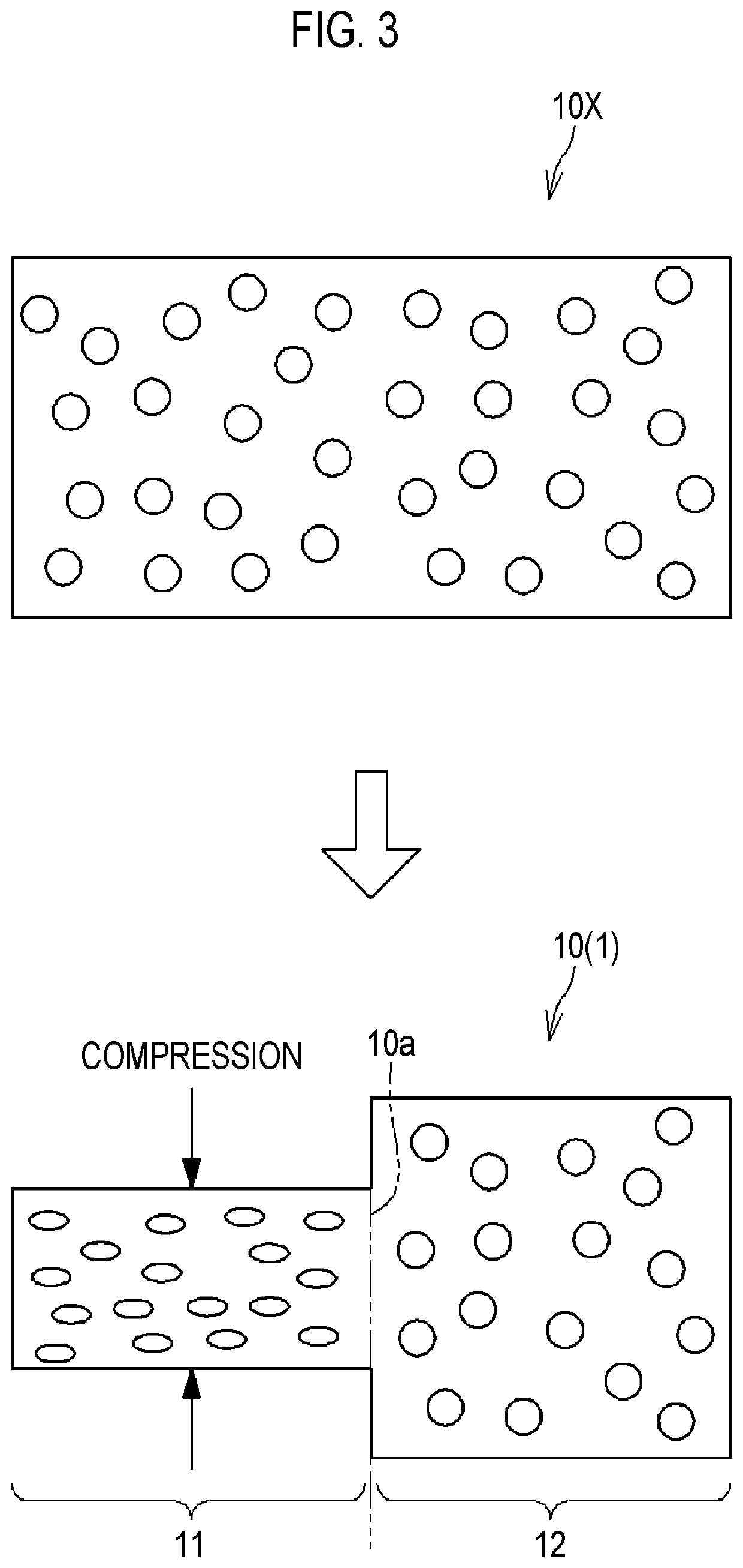
[0065]FIG. 3 is a schematic view showing a method for manufacturing the porous body 10 according to a The upper figure of FIG. 3 shows a porous material 10X that is a source of the porous body 10. The porous material 10X is a porous material in which continuous pores (pores) are formed. As the porous material 10X, it is preferable to use a material that can be plastically deformed, such as metal. Regarding the porous body 10 manufactured by this manufacturing method, when a desired mean pore diameter of the first porous portion 11 is the mean pore diameter φ1, and a desired mean pore diameter of the second porous portion 12 is the mean pore diameter φ2, the porous material 10X uses a porous material having the mean pore diameter φ2.

[0066]The lower figure of FIG. 3 shows the porous body 10 manufactured from the porous material 10X. In the method for manufacturing the porous body 10 according to the first embodiment, a portion of the porous material 10X is compressed such that the po...

second embodiment

[0070]FIG. 4 is a schematic view showing a method for manufacturing the porous body 10 according to a The upper figure of FIG. 4 shows a first porous material 10Y and a second porous material 10Z, which are the sources of the porous body 10. Regarding the porous body 10 manufactured by this manufacturing method, when a desired mean pore diameter of the first porous portion 11 is the mean pore diameter φ1, and a desired mean pore diameter of the second porous portion 12 is the mean pore diameter φ2, the first porous material 10Y uses the porous material having the mean pore diameter φ1 and the second porous material 10Z uses the porous material having the mean pore diameter φ2.

[0071]The lower figure of FIG. 4 shows the porous body 10 manufactured from the first porous material 10Y and the second porous material 10Z. In the method for manufacturing the porous body 10 according to the second embodiment, the porous body 10 is manufactured by bringing the first porous material 10Y and t...


PUM

PropertyMeasurementUnit
penetration depthaaaaaaaaaa
mean pore diameteraaaaaaaaaa
surface tensionaaaaaaaaaa

Abstract

A lubricant supply device includes a porous body including a first porous portion and a second porous portion in contact with the first porous portion, the porous body being impregnated with a lubricant. A penetration depth of the lubricant in the second porous portion is larger than a penetration depth of the lubricant in the first porous portion.

Description

CROSS-REFERENCE TO RELATED APPLICATION[0001]This application claims priority to Japanese Patent Application No. 2021-002255 filed on Jan. 8, 2021, incorporated herein by reference in its entirety.BACKGROUND1. Technical Field[0002]The present disclosure relates to a lubricant supply device, a method for manufacturing the same, and a rolling sliding device.2. Description of Related Art[0003]Japanese Unexamined Patent Application Publication No. 2017-133684 (JP 2017-133684 A) discloses a lubricant supply device capable of supplying a base oil contained in grease to a target portion. The lubricant supply device includes a lubricant storage member in which a storage chamber filled with grease is formed, and a permeation member made of a porous body having continuous pores. In the lubricant supply device, the base oil (lubricant) contained in the grease filling the storage chamber can be permeated into the permeation member, and the lubricant can be discharged little by little from the pe...

Claims


Application Information

Patent Timeline
Patent Type & Authority Applications(United States)
IPC IPC(8): F16C33/66F16C19/06
CPCF16C33/6648F16C19/06F16C33/6659F16C33/6655F16C33/783F16C33/7846F16C33/74F16C33/6611F16N2270/24F16N2210/14
Inventor KAMIYA, TORU
Owner JTEKT CORP
Features
  • R&D
  • Intellectual Property
  • Life Sciences
  • Materials
  • Tech Scout
  • Unparalleled Data Quality
  • Higher Quality Content
  • 60% Fewer Hallucinations
Learn More