Manufacturing a wind turbine blade shell part

a technology of wind turbine blades and shell parts, which is applied in the direction of electrical/magnetic measuring arrangements, instruments, measurement devices, etc., can solve the problems of blade scrapping, adverse effects, and general acceptance of ultrasound testing methods that are not sufficiently precise when used

Pending Publication Date: 2022-07-21
LM WINDPOWER
View PDF3 Cites 0 Cited by
  • Summary
  • Abstract
  • Description
  • Claims
  • Application Information

AI Technical Summary

Problems solved by technology

The inventors have found that the generally accepted ultrasound testing method is not sufficiently precise when used for determining whether a blade meets the required specifications or should be scrapped.
The lack of precision means that blades are scrapped even though they actually meet the specifications.
An ultrasound measurement may show that a blade is too

Method used


Image

  • Manufacturing a wind turbine blade shell part
  • Manufacturing a wind turbine blade shell part
  • Manufacturing a wind turbine blade shell part

Examples


Embodiment Construction

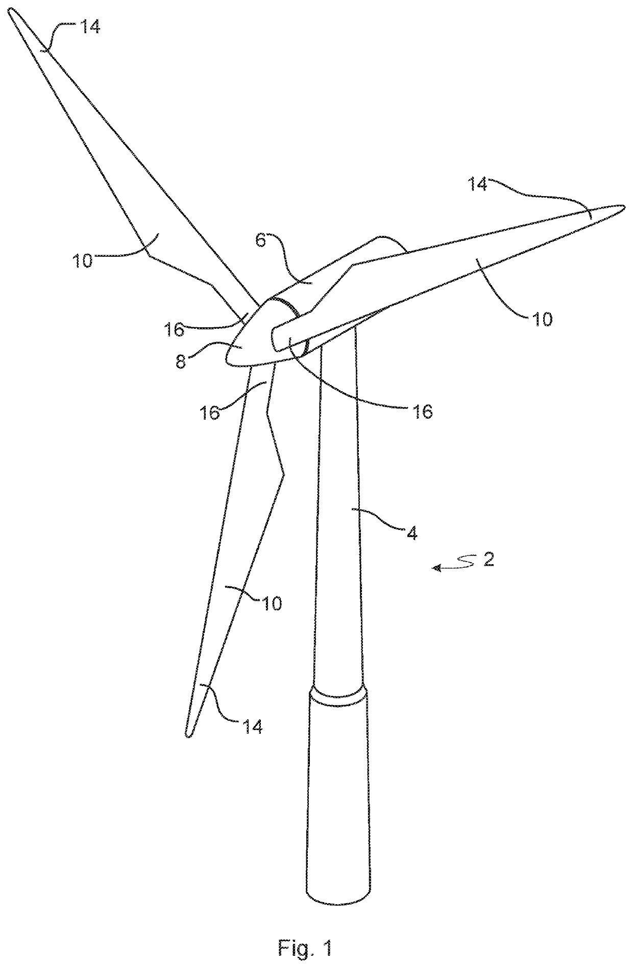
[0045]FIG. 1 illustrates a conventional modern upwind wind turbine 2 according to the so-called “Danish concept” with a tower 4, a nacelle 6 and a rotor with a substantially horizontal rotor shaft. The rotor includes a hub 8 and three blades 10 extending radially from the hub 8, each having a blade root 16 nearest the hub and a blade tip 14 furthest from the hub 8.

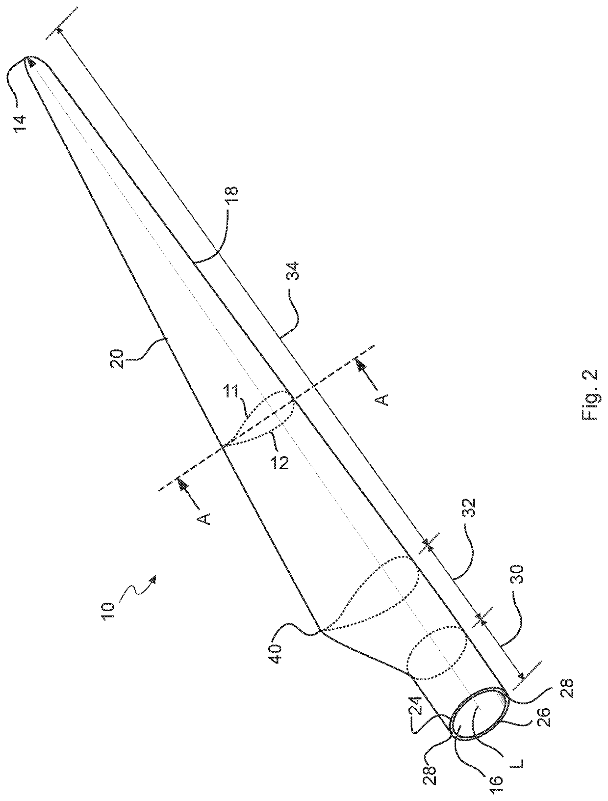
[0046]FIG. 2 shows a schematic view of an exemplary wind turbine blade 10. The wind turbine blade 10 has the shape of a conventional wind turbine blade with a root end and a tip end and comprises a root region 30 closest to the hub, a profiled or airfoil region 34 furthest away from the hub 8, and a transition region 32 between the root region 30 and the airfoil region 34. The blade 10 comprises a leading edge 18 facing the direction of rotation of the blade 10, when the blade is mounted on the hub, and a trailing edge 20 facing the opposite direction of the leading edge 18. The airfoil region 34, also called the profiled ...


PUM

PropertyMeasurementUnit
Lengthaaaaaaaaaa
Thicknessaaaaaaaaaa
Thicknessaaaaaaaaaa

Abstract

The present invention relates to a method for manufacturing a wind turbine blade part. The method comprises providing one or more wind turbine blade components including a wind turbine blade component comprising a fibre material element, an electrically conductive element, a magnetic field generator for generating an Eddy current in the electrically conductive element; arranging the electrically conductive element, the magnetic field generator, and the fibre material element such that at least a part of the fibre material element is positioned between the electrically conductive element and the magnetic field generator; generating an Eddy current in the electrically conductive element using the magnetic field generator; generating, using a magnetic sensor, a signal representing a magnetic field induced by the generated Eddy current, and forming the wind turbine blade part by assembling the wind turbine blade components.

Description

TECHNICAL FIELD[0001]The present invention relates to a method for manufacturing a wind turbine blade shell part comprising one or more wind turbine blade components including a wind turbine blade component comprising a fibre material element.BACKGROUND[0002]Wind turbine blades of fibre-reinforced polymer and in particular the aerodynamic shells of wind turbine blades are usually manufactured in moulds, typically by manufacturing the pressure side and the suction side of the blade separately by arranging glass fibre mats in each of the two mould parts. Then, the two sides are glued together, often by means of internal flange parts. Glue is applied to the inner face of the lower blade half before the upper blade half is lowered thereon. Additionally, one or two reinforcing profiles (beams) are often attached to the inside of the lower blade half prior to gluing to the upper blade half.[0003]The aerodynamic shell parts are typically made by use of Vacuum Assisted Resin Transfer Mouldi...

Claims


Application Information

Patent Timeline
IPC IPC(8): B29C70/54B29C70/88B29C70/34G01B7/06
CPCB29C70/54B29C70/885B29K2705/02G01B7/10B29C70/342B29C70/882B29C70/06B29L2031/085B29K2105/206B29K2705/10B29K2995/0005
Inventor JØRGENSEN, YA MINNIELSEN, LARSJESPERSEN, KLAVS
Owner LM WINDPOWER
Why Eureka
Try Eureka