Eureka AIR delivers breakthrough ideas for toughest innovation challenges, trusted by R&D personnel around the world.

Hybrid microjet liquid-cooled heat spreader

Pending Publication Date: 2022-07-21
PENN STATE RES FOUND
View PDF0 Cites 2 Cited by
  • Summary
  • Abstract
  • Description
  • Claims
  • Application Information

AI Technical Summary

Benefits of technology

The invention is a liquid cooling system for electronic components that uses impinging jets to improve heat transfer. The system includes an inlet fractal manifold and an outlet manifold that work together to distribute fluid evenly and collect the exiting fluid in the same plane as the inlet flow. The system is designed to improve the thermal performance of the system and can be easily attached to different computer configurations. The technical effects of the invention include improved heat transfer and a more uniform distribution of fluid.

Problems solved by technology

Moreover, Brunshwiler et. al [17] showed that high-performance microjet thermal management systems required interspersed fluid removal, resulting in complex interconnected 3-D flow networks.

Method used


Image

  • Hybrid microjet liquid-cooled heat spreader
  • Hybrid microjet liquid-cooled heat spreader
  • Hybrid microjet liquid-cooled heat spreader

Examples


Embodiment Construction

[0097]Reference will now be made in detail to the preferred embodiments of the present invention, examples of which are illustrated in the accompanying drawings. Wherever possible, the same reference numbers will be used throughout the drawings to refer to the same or like parts. In addition, although the terms used in the present invention are selected from generally known and used terms, some of the terms mentioned in the description of the present invention have been selected by the applicant at his or her discretion, the detailed meanings of which are described in relevant parts of the description herein. Furthermore, it is required that the present invention is understood, not simply by the actual terms used but by the meaning of each term lying within.

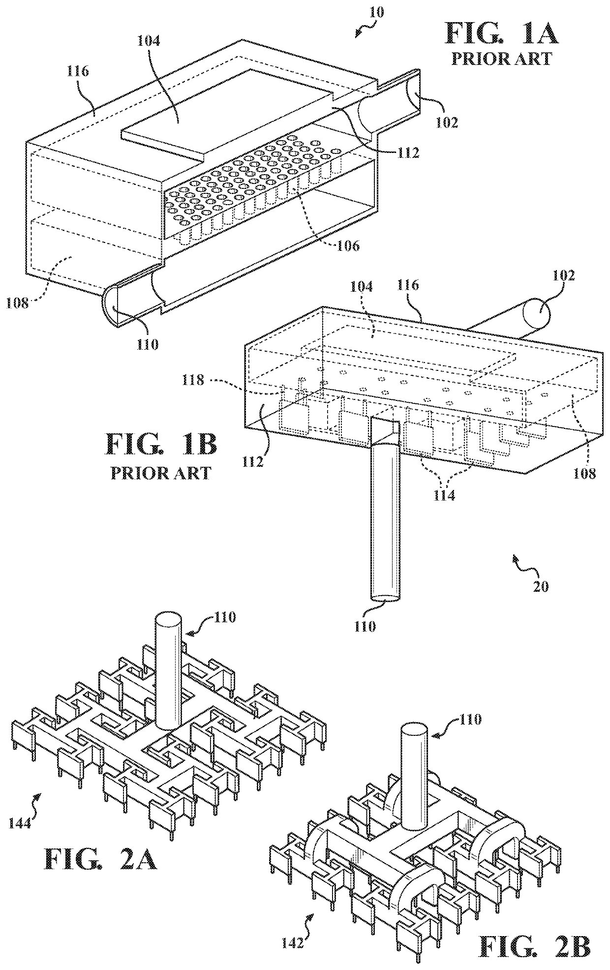
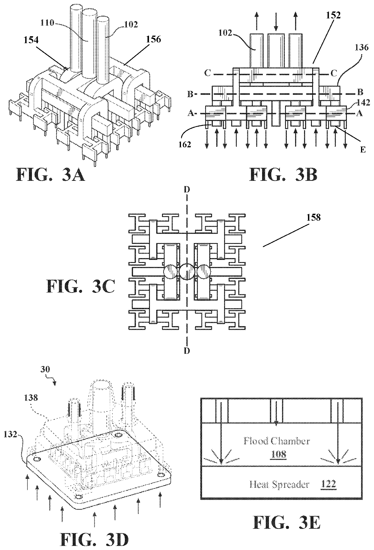
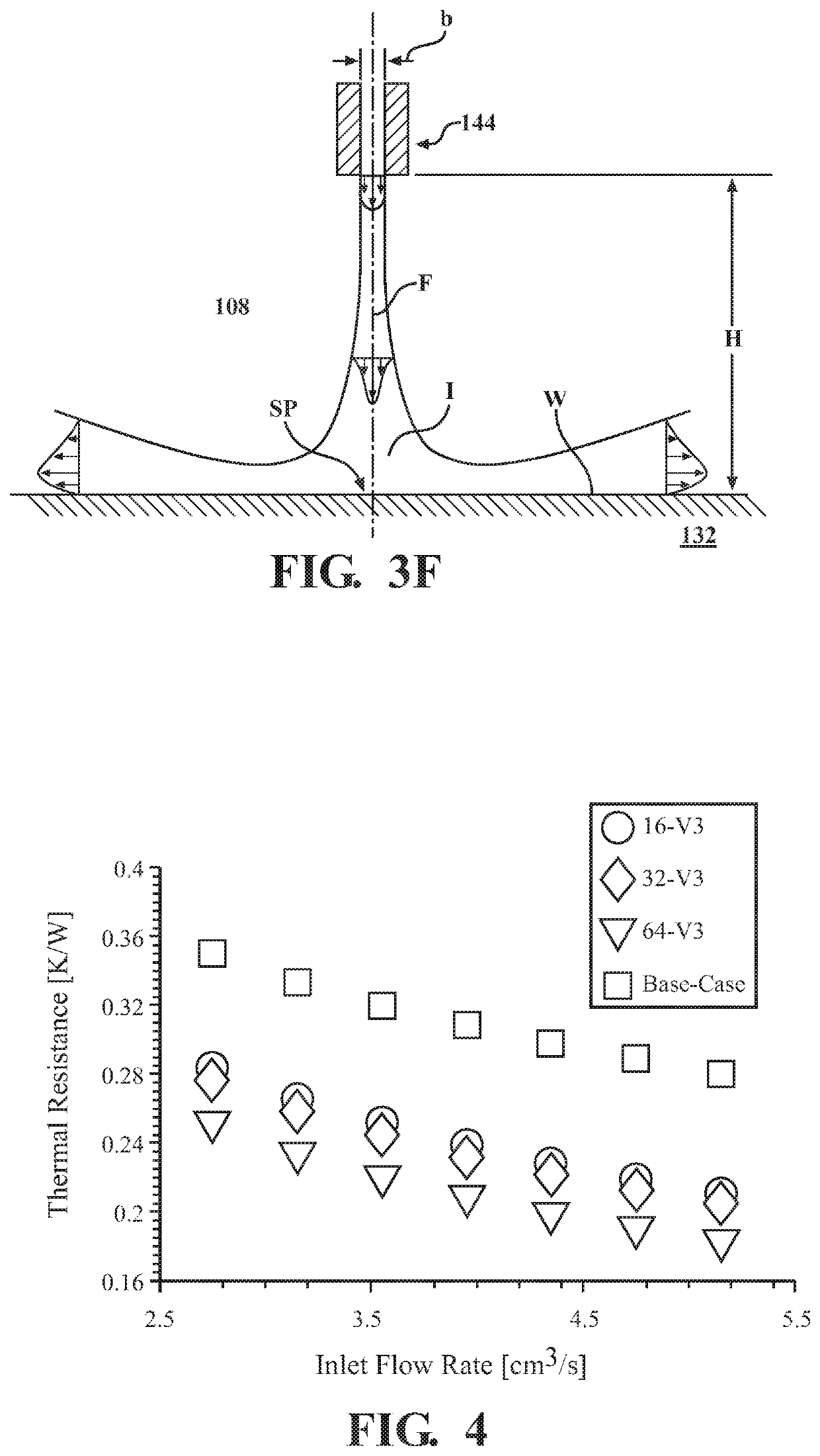
[0098]A parametric optimization of a novel hybrid configuration of liquid-cooled heat sinks is presented herein. Such a hybrid design encompasses a combination of channels and microjets for optimal performance of chip scale high-...


PUM


Abstract

A liquid-cooled heat sink has three parts: the water block, the X-clamp, and a copper plate. The water block has an inlet connected to a resin shell. Inside the shell, a fractal inlet manifold divides the inlet coolant flow into several sub streams that eventually exit in the form of uniformly distributed liquid jets through small nozzles / microjets at the bottom of the shell. The union between the shell and the copper plate forms a flood chamber, where the jets impinge on the copper plate, dissipating the heat supplied to the copper plate in contact with the heat source. The warm liquid is removed from the flood chamber through an outlet manifold embedded with the resin shell.

Description

REFERENCE TO RELATED APPLICATION[0001]This application is the U.S. National Stage of PCT / US2020 / 027887 filed Apr. 13, 2020, which claims priority to U.S. Provisional Patent Application Ser. No. 62 / 832,652, filed Apr. 11, 2019, the entire content of both are incorporated herein by reference in their entirety.FIELD OF THE INVENTION[0002]This invention relates to the field of liquid cooled heat sinks used for cooling of electronic components.BACKGROUND OF THE INVENTION[0003]In the light of the fast-paced development track of microscale electronics, such as CPU chips and LED arrays, thermal management has emerged as a vital element in the operation of such devices. The heat generation in multiscale microsystems initiates at the interconnect level and progresses over subsequent length scales [1], where the interconnect level heat transfer analysis is comprehended using mainstream nanoscale heat transfer [2]. With microscale systems as next in the scale order, the need for effective therm...

Claims


Application Information

Patent Timeline
IPC IPC(8): H05K7/20F28F3/12F28D1/02
CPCH05K7/20263H05K7/20254H05K7/20272F28D2021/0029F28F3/12F28D1/0246H05K7/20236H01L23/4735H01L23/3677F28F7/02B33Y80/00
Inventor ALVARADO, BLADIMIR RAMOSVALLE, CARLOS ULISES GONZALEZGUERRA, LUIS ENRIQUE PANIAGUAVELI, JONATHAN
Owner PENN STATE RES FOUND
Why Eureka
Eureka Blog
Learn More