
Brake system

a brake system and brake technology, applied in the direction of brake systems, brake components, transportation and packaging, etc., can solve the problems of electric parking brake devices, electric parking brake devices have been experienced, and the operation of lock operation needs to be considerably complicated

Pending Publication Date: 2022-07-28
TOYOTA JIDOSHA KK
View PDF0 Cites 0 Cited by
  • Summary
  • Abstract
  • Description
  • Claims
  • Application Information

AI Technical Summary

Benefits of technology

The present patent is about improving electric parking brakes by integrating them into hydraulic brakes. The invention uses a supply current to the electric motor as an index indicative of the braking force generated by the lock operation. The timing of the re-lock operation is estimated based on a map that represents a relationship between a lapse of time and a decrease in the braking force. The invention also addresses the problem of high temperatures during the initial lock operation and proposes a solution to reduce the number of lock operations and the load on the actuator and wheel brake device. The brake system according to the invention can be used in a hydraulic-braking-force monitor mode to optimize the lock operation and detect malfunctions of the brake system. The invention also provides a configuration for starting the parking brake control with a larger hydraulic braking force to allow enough time for execution of the parking brake control.

Problems solved by technology

In a case where the temperature when the lock operation is initially performed, namely, the temperature when the parking brake is activated, is considerably high, the lock operation needs to be performed considerably large number of times, undesirably imposing a large load on the electric parking brake device.
This problem is one of problems that the electric parking brake device has been experienced.

Method used


Image

  • Brake system
  • Brake system
  • Brake system

Examples


Embodiment Construction

[0039]Referring to the drawings, there will be explained in detail a brake system according to one embodiment of the present disclosure. It is to be understood that the present disclosure is not limited to the details of the following embodiment but may be embodied based on the forms described in Various Forms and may be changed and modified based on the knowledge of those skilled in the art.

A. Overall Configuration of Brake System

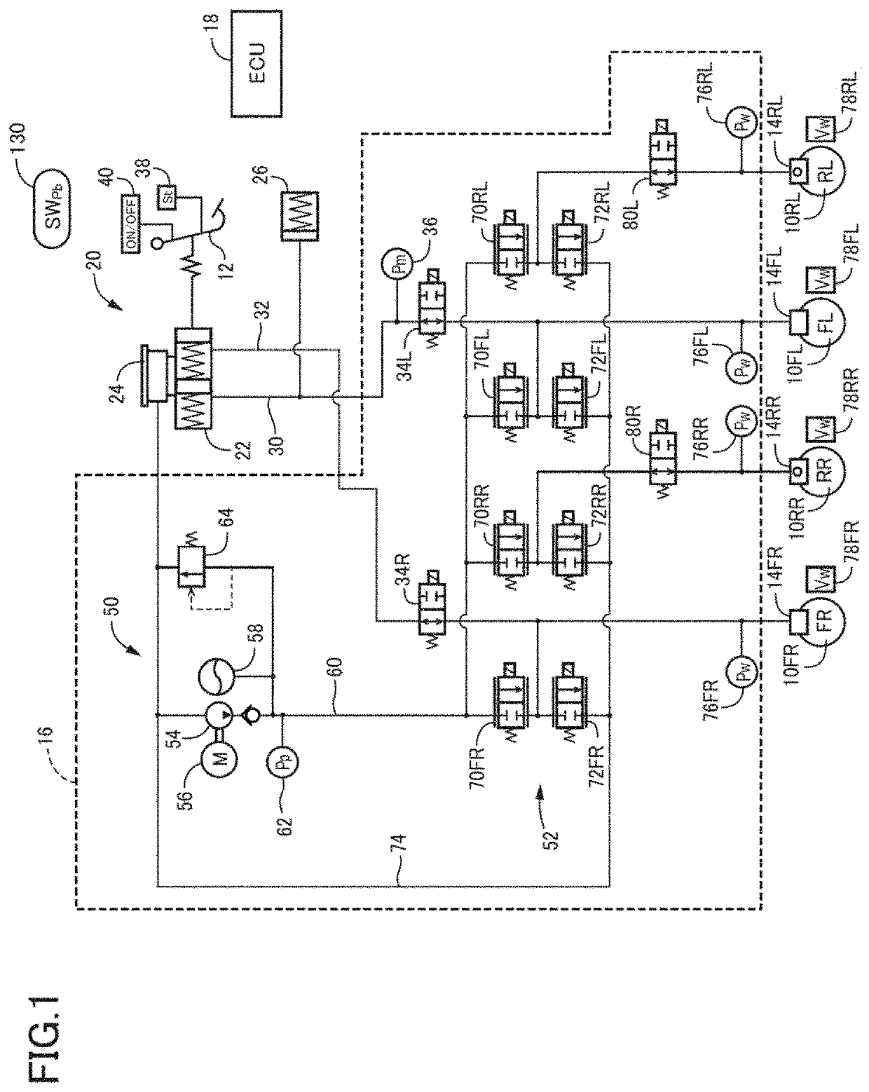
[0040]As illustrated in FIG. 1, a brake system according to the present embodiment is basically a hydraulic brake system configured to apply a braking force to each of a front left wheel 10FL, a front right wheel 10FR, a rear left wheel 10RL, and a rear right wheel 10RR. The present brake system is an ordinary system except a parking brake function that will be later explained, and an explanation relating to the hydraulic system will be briefly made. In the following explanation, each of the front left wheel 10FL and the front right wheel 10FR will be refe...


PUM


Abstract

A vehicle brake system, including: a wheel brake device including an actuator including a piston, a working fluid chamber, an electric motor, and a piston moving mechanism; a working-fluid supply device; and a controller configured to execute: a normal brake control to control a hydraulic braking force to a magnitude corresponding to a braking request; and a parking brake control to cause the wheel brake device to be operated as a parking brake, wherein, in the parking brake control, the controller controls the wheel brake device to generate the hydraulic braking force at a start timing of an operation as the parking brake, controls the actuator to perform a lock operation in which the electric motor is operated to move the piston forward in a state in which the hydraulic braking force is generated, and controls the wheel brake device to release the hydraulic braking force after the lock operation.

Description

CROSS REFERENCE TO RELATED APPLICATION[0001]The present application claims priority to Japanese Patent Application No. 2021-011267, which was filed on Jan. 27, 2021, the disclosure of which is herein incorporated by reference in its entirety.BACKGROUNDTechnical Field[0002]The following disclosure relates to a vehicle brake system having a parking brake function.Description of Related Art[0003]An electric parking brake device is configured to generate a braking force for a wheel by performing an operation in which a piston is moved in dependence on a force of an electric motor so as to cause friction members, such as brake pads, to be pressed against a rotary member, such as a disc rotor, that rotates with the wheel. This operation of the electric parking brake device will be hereinafter referred to as “lock operation” or “clamp operation” where appropriate. The temperature of the electric parking brake rises during driving of the vehicle in which a driver sometimes applies brakes. E...

Claims


Application Information

Patent Timeline
IPC IPC(8): B60T13/58B60T17/22
CPCB60T13/588B60T2270/406B60T17/221B60T13/745B60T13/741B60T7/042B60T17/22B60T13/662F16D2127/06
Inventor YABUSAKI, NAOKIANDOU, TSUYOSHI
Owner TOYOTA JIDOSHA KK
Learn More