Method for operating a machine tool and machine tool

Pending Publication Date: 2022-08-11
HILTI AG
View PDF0 Cites 0 Cited by
  • Summary
  • Abstract
  • Description
  • Claims
  • Application Information

AI Technical Summary

Problems solved by technology

However, a mechanical coupling is characterized by a high weight, requires space, and has a negative impact on the manufacturing costs of the machine tool.
In addition, the mechanical components are subject to wear and may need to be serviced or replaced.
Wear of the mechanical coupling can disadvantageously change a release torque of the coupling, such that a maximum possible release torque of the co

Method used


Image

  • Method for operating a machine tool and machine tool
  • Method for operating a machine tool and machine tool
  • Method for operating a machine tool and machine tool

Examples


Example

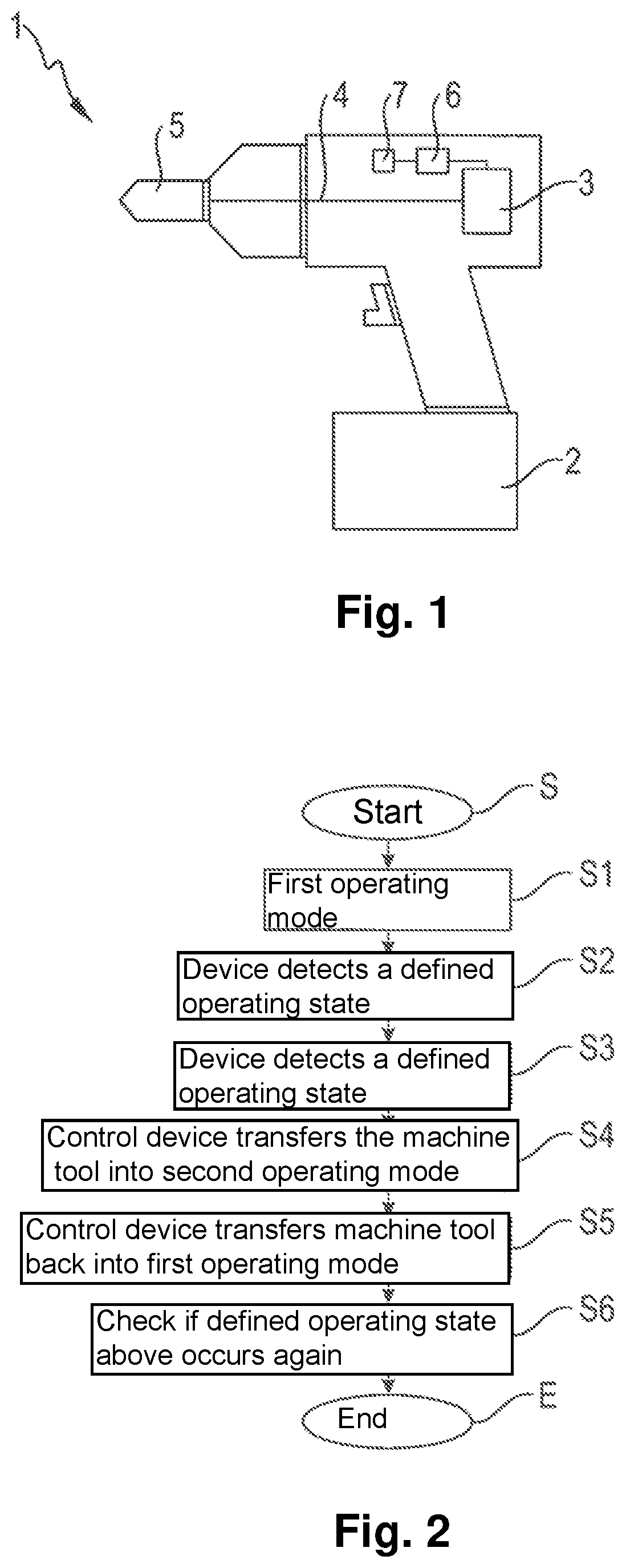
[0039]FIG. 1 is an exemplary flow diagram of an embodiment of a method according to the invention for operating a machine tool 1, in particular a cordless screwdriver, a drilling machine or the like. The machine tool 1 has a battery 2, which is provided in order to supply power to an electric motor 3 of the machine tool 1. The electric motor 3 is designed to rotationally drive an output shaft 4 of the machine tool 1, it being possible for the output shaft 4 to be coupled to a tool 5, for example a bit, a drill or the like. The machine tool 1 also has a control device 6 for actuating the electric motor 3, the control device 6 being designed to actuate the electric motor 3 in a controlled manner on the basis of an amperage. The machine tool 1 also has a device 7 for determining a parameter of the machine tool 1, in particular a torque applied to the output shaft 4 and / or an acceleration value of the output shaft 4. The machine tool 1 is designed so as to not have a mechanical coupling...


PUM

PropertyMeasurementUnit
Fractionaaaaaaaaaa
Fractionaaaaaaaaaa
Fractionaaaaaaaaaa

Abstract

A method for operating a machine tool having a battery and an electric motor which is designed to rotationally drive an output shaft that can be coupled to a tool is described, a control device for actuating the electric motor and a device for determining a parameter being provided, it being possible for the machine tool to be operated in a first operating mode and a second operating mode, and the control device transferring the machine tool from the first operating mode into the second operating mode if the parameter determined by the device exceeds or falls below a defined threshold value. The electric motor (3) is controlled in the second operating mode by an amperage profile comprising current pulses (10, 10′, 11), a level a maximum amperage (A1, A1′, A2) of the current pulses (10, 10′, 11) being varied depending on an actual charge status of the battery (2). A machine tool that can be operated using a method of this kind is also described.

Description

[0001]The present invention relates to a method for operating a machine tool having a battery and an electric motor. Furthermore, the present invention relates to a machine tool.BACKGROUND[0002]In machine tools known from practice, which are designed to have a regulated electric motor that can be operated by a battery, an output torque applied to an output shaft increases and thus a motor current required to provide this output torque increases, for example when drilling a hole of which the drilling depth increases, in order to provide the correspondingly increasing output torque and to maintain a desired rotational speed of a rotor of the electric motor. If a braking torque applied to the output shaft surpasses a performance capacity of the electric motor, the rotor stops, even if the motor current increases. The locked rotor and the high amperage that is applied can damage the electronics and / or the electric motor if there is no hardware protection or software protection present. ...

Claims


Application Information

Patent Timeline
IPC IPC(8): B25F5/00B23B45/00
CPCB25F5/001B25B23/1475B23B45/008B23B45/02B25B21/00B25F5/00H02P29/40H02P29/20B25B23/1456
Inventor LIU, QINGILLMEIER, BERNDSCHMID, STEFAN
Owner HILTI AG
Why Eureka
Try Eureka